


P A G E 20
E a s y P I C v 8 f o r P I C 2 4 / d s P I C 3 3
M a n u a l
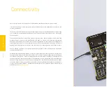
C O N N E C T I V I T Y
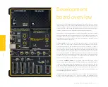
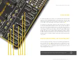
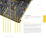
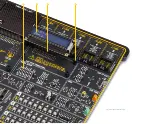
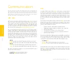
INPUT/OUTPUT section
I/O pins of any MCU are internally grouped as PORTs. The same grouping concept is
kept throughout the development board as well, offering a clean and organized user
interface.
There are three PORTs
(1)
on the EasyPIC v8 for PIC24/dsPIC33 development board,
labeled from PORTA to PORB. Depending on the pin-count of the MCU, not all PORTs
will be used. However, the development board supports the highest pin-count MCUs in
DIP package type (28 pins). The PORTs are located at the lower right side of the board,
each containing a set of buttons, LEDs, an eight-pole DIP switch, and a single 2x5 pin
header with the standard 2.54mm pitch. The PORTs are labeled according to the MCU
PORT they are routed to.
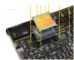
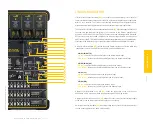
PORT buttons
PORT buttons
(2)
can be used to apply an arbitrary logic state to the pins of the MCU.
These buttons are small tactile SPST buttons that work in combination with a DIP
switch (SW4), labeled as BUTTON. This DIP switch is located in the BOARD SETUP
section.
BUTTON PRESS LEVEL
This four-pole, tri-state DIP switch allows the button to apply a LOW logic level to an
MCU pin when pressed (connecting it to the GND), or to apply a HIGH logic level when
pressed (connecting it to the power rail). It can also be used to completely disconnect
the button, preventing accidental button presses. To limit the pin current and prevent
the excessive inrush of currents when a button is pressed, a protective 220
Ω
resistor
is used, connected in series with the switch. Each position of the BUTTON PRESS
LEVEL
(3)
is used to determine the applied logic level of a button press for the entire
PORT. As a result, only three poles of this DIP switch are used, allowing control of all
three groups of buttons (unused poles are marked with the NC label - Not Connected).
BUTTON PRESS LEVEL:
UP position:
a button press applies HIGH logic level to the corresponding PORT pins
MID position:
a button is completely disconnected
DOWN position:
a button applies LOW logic level to the corresponding PORT pins
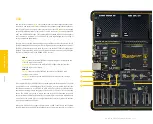
UP-PULL-DOWN switch
Besides buttons, each of the three PORTs has an eight-pole DIP switch associated
with it. It is labeled as UP-PULL-DOWN
(4)
and it is used to enable a pull-up or pull-
down resistor for the specific pin or to leave the pin in a floating state:
UP-PULL-DOWN:
UP position:
connects a 4.7k
Ω
resistor between the MCU power rail and the pin (the
pin is pulled up)
MID position:
Disables both pull-up and pull-down resistor connections from the
pin (the pin is in the floating state)
DOWN position:
Connects the 4.7k
Ω
resistor between the GND and pin associated with
the DIP switch position (the pin is pulled down)
PORT LEDs
Each PORT contains a group of maximum eight LEDs
(5)
used to provide a visual
indication of the logic state of the specific pin. The maximum current through a
single LED is limited with the 4.7k
Ω
resistor. Each LED is connected to a PORT pin
and it is labeled according to the name of the connected pin. LEDs on each PORT
should be disconnected when not used. Having a LED on a communication line or an
A/D converter input might alter expected results since LED represents an additional
electrical load. There is a ten-pole DIP switch (SW6)
(6)
located in the BOARD SETUP
section. Three poles of this DIP switch, labeled as PORT LEDs are used to enable or
disable LEDs on each PORT:


