


Mi|Home Lighting Controls (MIHO0 0 8, MIHO0 24,
MIHO0 25, MIHO0 26)
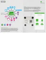
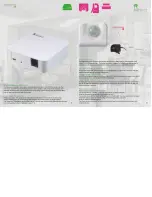
The Mi|Home lighting range consists of a single switch, master and
slave switch, double wall switch and a dimmer. All switches are available
in White, Polished Chrome, Brushed Steel and Black Nickel. The range
includes screwless replaceable face plates. All switches are retroî t in
suitably deep pattress boxes (25mm depth or deeper).
FAQs about the Light Switches
Are the switches retroî t? Yes
What is the maximum load they can switch? The switches are capable of
switching up to 250 W.
Do the switches work with LED bulbs? Yes, however we recommend that
you have at least two LED bulbs in series and use quality, dimmable LED
bulbs with the system. We have tested leading UK brands successfully.
Do the switches î t in 25mm pattress boxes? Yes, though top and bottom
lugs must be removed.
Do the Switches require a neutral wire? No, they switch live only.
Do the switches feedback status? No
Slave
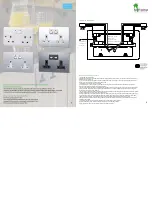
MIHO0 0 8 Light Switch & Slave Switch
Fitting and Wiring Instructions
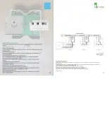
1). Before commencing work, isolate the mains power supply and remove the fuse in the fuse box or switch oǺ the circuit breaker in the
consumer unit.
2). If unit is to be used as a replacement for an existing product, remove existing unit from its location and disconnect the wiring.
3). This item will not î t into a 4 lug box. If such a box has been previously installed the top and bottom lugs should be removed or bent back to
avoid contact with the interior.
4). Connect the wires as shown in appropriate wiring diagrams above. Use green/ yellow sleeving on earth conductors that are not insulated.
Ensure terminals are properly tightened and no bare wire is visible. Push back unit into mounting box making sure conductors are not trapped.
5). Screw the unit module to the mounting box, please ensure screws are suǸ ciently tight to support the product but please do not over tighten
as this may cause some deformation.
6). If the product has a decorative front cover plate over the module, place the cover plate over the module and press î rmly top and bottom
until all retaining clips have fully clipped into position. To remove the decorative front cover plate, carefully insert a 3mm terminal screwdriver
into the bottom slots and lift upward until all the retaining clips disengage from the plastic module moulding. Please ensure the decorative
plate is held as it is released to avoid it being dropped and damaged.
7). To reduce the risk of discolouration or tarnishing, avoid installation on damp plaster.
8). These products must be installed in accordance with the latest Building and IET
wiring regulations. If in any doubt, please contact a qualiî ed electrician.
7
Typical Application 1 Way Switching
250 W RF Switch
Typical Application 2 Way Switching
(Appropriate RF Slave switch
must be wired for this application)
250 W Switch
MASTER
MASTER
SLAVE