24
TS571W Installa
tion Instructions
TS571W Installa
tion Instructions
25
1
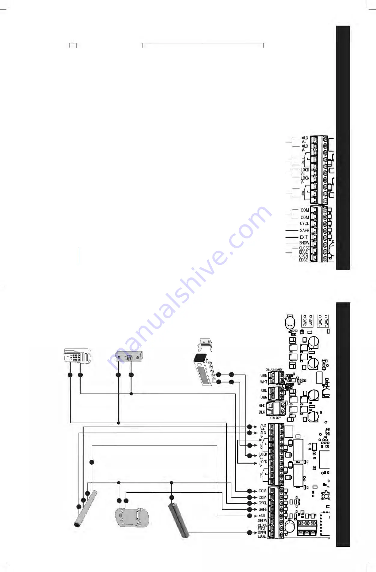
COM:
Common/Negative terminal for accessory devices and negative wir
e fr
om solar panel(s).
2
CYCL:
(T
ypically for use with doorbell button or har
d wir
ed keypad)
•
Each activation at this input will cycle the operation as follows:
….
→
OPEN
→
STOP
→
CLOSE
→
STOP
→
OPEN
→
…
3
SAFE:
(T
ypically for use with photo beam device,loop detector or other non-contact sensors)
•
Activation
of
this input while
the gate is closing,
or
at
a
position
other
than
fully
open
or
fully
closed
will cause the gate to stop and r
etur
n to the opened position.
•
Activation of this input while the gate is opening has no ef
fect. (gate will continue to open)
•
Activation of this input while the gate is open will pr
event gate fr
om closing.
•
Activation of this input while at open limit will r
estart the auto close time (if enabled).
4
EXIT
:
(T
ypically for use with exit loop or wand)
•
Activation of this input will open the gate if it’
s not alr
eady at the open position.
•
Activation of this input while at open limit will r
estart the auto close time (if enabled).
5
SHD
W:
(T
ypically for use with loop detector device)
•
This input is only monitor
ed when the gate is at the fully open at the open position.
At any other position, activation of this input has no ef
fect on gate operation.
•
Activation of this input while gate at the fully open position will pr
event gate fr
om closing.
6
EDGE:
(T
ypically for use with contact edge sensor)
•
Activation of this input while gate is moving will cause it to r
everse dir
ection for 2 seconds.
•
Activation of this input while idle will pr
event gate fr
om running.
NOTES:
●
All
ACCESSOR
Y INPUTS (ITEMS 2-6) are dr
y
contact,normally open inputs.
DO NOT a
pply
external volta
ge inputs to these terminals.
●
All
ACCESSOR
Y INPUTS (ITEMS 2-6) are
connected with respect to the COMMON
terminals (ITEM 1).
LOCK
OUTPUTS
ACCESSORY INPUTS
CONTROL BO
ARD CONNECTIONS
Photo Beams
Mighty Mule
Push Button Control
Mighty Mule
V
ehicle Sensor
Refer to V
ehicle Sensor
manual for additional
information if needed.
Edge Sensor
Automatic Gate Lock (FM143)
NOTE:
Connections ar
e for typical applications.
For additional connection options not illustrated
her
e r
efer to the accessory manual for details.
6
3
8
4
8
Mighty Mule Keypad
1
2
8
9
8
Red
Blue
Black
Shield
Yellow
10
3
5
6
10
9
3
4
5
6
7
+
+
-
-
+
-
For FM130/FM130-SW and FM136,
see
Appendix
A in this manual.
CONNECTING A
CCESSORIES
7
AUX V+
& AUX V
-:
These terminals provide constant auxiliar
y accessor
y po
wer from the opera
tor's ba
tter
y, ra
ted
for 2 amps MAX.
The output is designed to be used in conjunction with the
AUX relay
, ITEM 8.
NO
TE:
Using this po
wer output will drain your opera
tor ba
tter
y. Continuous use grea
ter than 20mA is NOT recommended for solar
applica
tions.
8
AUX Relay:
The
AUX Relay is triggered during ga
te opera
tion and remains activa
ted for the dura
tion of the ga
te
opera
tion.
The
AUX Relay should only be used for s
witching
AUX
V-.
9
LOCK
V+ & LOCK
V-:
These terminals are designed for use with the
Automa
tic Ga
te Lock (FM143).
See
pa
ge 27
of
this manual for connection dia
gram.
10
LOCK Relay:
The LOCK Relay is designed for use with the
Automa
tic Ga
te Lock (FM143).
This relay is momentarily
triggered a
t the beginning of each ga
te opera
tion.
See pa
ge 27 of this manual for connection dia
gram.
The LOCK
Relay should only be used for s
witching LOCK
V-.
NO
TE:
DO NOT connect positive volta
ge to the
AUX or LOCK Relays.


