background image


Technical Information


T300 Series Clothes Dryer (Condenser) 


1.0 

Construction and Design 


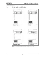
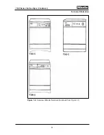
Figure 1-1: 

Overview of Model Numbers (Continued on Figure 1-2)


Summary of Contents for T300

Page 1: ...t is used internationally and is provided for general guidance and informational purposes only Information may contain omissions and or additional data for some USA models If you have any questions require clarification or need assistance contact the Miele Technical Support Center at 1 888 529 8790 2007 Miele USA ...

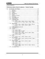
Page 2: ... 369 C 2 T 377 C T 378 C T 382 C T 383 C T 388 C 12 1 12 2 T 368 C 12 1 13 Condensate Container Drawer 12 1 14 Condenser Box 12 1 15 Controls 12 1 15 1 T 368 C T 369 C 12 1 15 2 T 368 C T 369 C 2 T 382 C 12 1 15 3 T 377 C T 378 C T 388 C 13 1 15 4 T 352 C T 358 C T 359 C T 367 C T 368 C T 369 C T 369 C 2 T 382 C T 388 C 13 1 15 5 T 377 C T 378 C 13 1 16 Buzzer 13 1 16 1 T 352 C T 357 C T 358 C T 3...

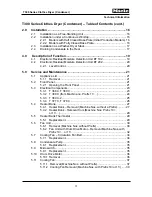
Page 3: ...1 Removal 21 5 2 Front Panel 21 5 2 1 Opening the Front Panel 21 5 3 Electrical Components 23 5 3 1 T 368 C T 369 C 23 5 3 2 T 368 C from Machine no Prefix 11 24 5 3 3 T 369 C 2 25 5 3 4 T 377 C T 378 C 26 5 4 Heater Bank 27 5 4 1 Heater Bank Removal Machine Nos without a Prefix 27 5 4 2 Heater Bank Removal from Machine Nos Prefix 10 or 11 29 5 5 Heater Bank Thermostat 29 5 5 1 Replacement 29 5 6 ...

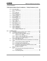
Page 4: ... 0 Fault Diagnosis 49 6 1 Checking the Sensor Controls T 377 C T 378 C 49 6 2 Checking Residual Moisture Stages 50 6 2 1 T 368 C T 369 C with EF 102 EF 202 Tester Part no A5300 50 6 2 2 T 377 C T 378 C with EPW 304 52 6 2 3 T 368 C T 369 C 2 with EF 202 Tester A5300 53 6 2 4 Testing the Level Switch Function 56 6 3 Temperature Measurements 57 6 3 1 Temperature Measurements Using a Maximum Thermome...

Page 5: ...ntainer Drawer 61 6 7 1 Drawer Cannot be Fully Closed 61 6 7 2 Water Container Does Not Locate Correctly When Pushed In and Opens Again 61 6 8 Dryer Fails to Operate 62 6 8 1 Control Lamp Lights Up But Dryer Fails to Operate 62 6 9 Faulty Program Sequence 63 6 9 1 Program Skips and Advances Too Quickly 63 6 9 2 Drying Stops in Mid Program 63 6 9 3 Dryer e g T 368 C With Timer MTA 2123 64 6 10 Loud...

Page 6: ...ne Nos Prefix 10 or 11 29 Figure 5 9 Fan Unit Removal 1 30 Figure 5 10 Fan Unit Removal 2 31 Figure 5 11 Fan Unit with Drum Drive Motor Removal 32 Figure 5 12 Removing the Drive Belt 33 Figure 5 13 Removing the Pump 33 Figure 5 14 Removing the Unit 34 Figure 5 15 Condensate Pump Replacement 35 Figure 5 16 Drum Drive Motor Removal 36 Figure 5 17 Cooling Fan Removal 1 Machine Nos without Prefix 37 F...

Page 7: ...on 11 Table 1 3 Consumption Data 15 Table 2 1 Stacking Kits 17 Table 6 1 Checking the Sensor Controls T 377 C T 378 C 49 Table 6 2 Test Module Setting 1 50 Table 6 3 Test Chart 51 Table 6 4 T 377 C T 378 C with EPW 304 52 Table 6 5 Test Chart 55 Table 6 6 Testing the Level Switch Function 56 Table 6 7 Temperature Range 57 Table 6 8 Replacement Bearing Part Numbers 60 7 ...

Page 8: ...Technical Information T300 Series Clothes Dryer Condenser 1 0 Construction and Design Figure 1 1 Overview of Model Numbers Continued on Figure 1 2 8 ...

Page 9: ...Technical Information T300 Series Clothes Dryer Condenser Figure 1 2 Overview of Model Numbers Continued from Figure 1 1 9 ...

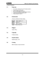
Page 10: ...t Free standing appliance with laminated worktop Can be built under with additional kit Fully opening front panel 1 2 Dimensions Values in brackets exclude worktop Height 85cm 82cm 1 Width 59 5 cm Depth 60 cm 57cm Table 1 1 Product Dimensions 1 3 Weight Approx 60kg 1 4 Capacity 5 0kg dry laundry 1 5 Drum Volume Stainless Steel 103 l 1 6 Casing MIELE single coat direct enameled 10 ...

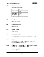
Page 11: ...with fan 240 W 1 9 Air Circulation Fan 160 W 130 m3 h 1 10 Cooling Air Fan 110 W 320 m3 h 1 11 Condensate Pump Condensate may be drained to the rear Refer to Section 1 12 Rear Drainage 1 11 1 T 368 C 20 W Rear drainage not possible until Machine no 700201 From Machine no 7100202 as Section 1 11 2 1 11 2 T 352 C T 358 C T 359 C T 367 C T 368 C T 369 C T 369 C 2 T 377 C T 378 C T 382 C T 383 C T 388...

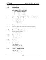
Page 12: ...3664 1 12 1 T 352 C T 358 C T 359 C T 367 C T 369 C T 369 C 2 T 377 C T 378 C T 382 C T 383 C T 388 C Spares Drainage Hose 1 5m Hose holder Hose spout 1 12 2 T 368 C Condensate drainage kit available from the Spares Department 1 13 Condensate Container Drawer Volume Approx 3 7 or 4 0 l 1 14 Condenser Box Volume Approx 0 6 l 1 15 Controls 1 15 1 T 368 C T 369 C Timer MTA 2123 Electronic Module EF 1...

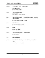
Page 13: ...lectronic Module EPW 304 1 15 4 T 352 C T 358 C T 359 C T 367 C T 368 C T 369 C T 369 C 2 T 382 C T 388 C Temperature Selector Normal or Low 1 15 5 T 377 C T 378 C Selector pad Low Temperature 1 16 Buzzer Variable Min Max 1 16 1 T 352 C T 357 C T 358 C T 359 C T 383 C Selectable On Off 1 17 Drum Lightning 1 17 1 T 358 C T 359 C T 367 C T 369 C 2 T 378 C T 382 C T 383 T 388 C Bulb E 14 15 W 220 V 3...

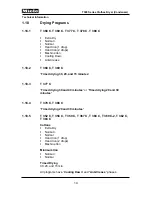
Page 14: ... 369 C Timed drying 30 20 and 15 minutes 1 18 3 T 377 C Timed drying 30 and 40 minutes or Timed drying 20 and 30 minutes 1 18 4 T 378 C T 388 C Timed drying 20 and 30 minutes 1 18 5 T 352 C T 358 C T 359 C T 367 C T 368 C T 369 C 2 T 382 C T 383 C Cottons Extra Dry Normal Normal Hand Iron 1 drop Hand Iron 2 drops Machine Iron Minimum Iron Normal Normal Timed Drying 30 20 and 15 min All programs ha...

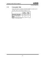
Page 15: ... Condenser 1 19 Consumption Data Values determined in accordance with DIN 0044986 Laundry spun at 1200 rpm reduces consumption by approx 25 Load 4 5 kg Load 5 0kg Drying Time minutes 76 83 Energy Consumption kWh 3 6 4 0 Table 1 3 Consumption Data 15 ...

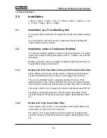
Page 16: ...Closed Base Plate Initial Production Models These models can be built in under certain conditions It is essential to ensure that sufficient air can be taken in at the rear of the machine They may be installed next to a washing machine However if the washing machine has a décor panel front then the service panel sealing strip should not be fitted so that air intake can also take place in this area ...

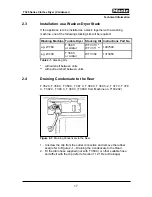
Page 17: ...lar WTV 302 1313950 Table 2 1 Stacking Kits without shelf between units with pull out shelf between units 2 4 Draining Condensate to the Rear T 352 C T 358 C T 359 C T 367 C T 369 C T 369 C 2 T 377 C T 378 C T 382 C T 383 C T 388 C T 368 C from Machine no 7100202 Figure 2 1 Draining Condensate to the Rear 1 Unscrew the clip from the outlet connection and remove the rubber seal refer to Figure 2 1 ...

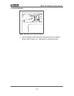
Page 18: ...nformation T300 Series Clothes Dryer Condenser Figure 2 2 Opening the Condenser Drawer 3 Use the stopper to close the water inlet opening to the condenser drawer refer to Figure 2 2 Opening the Condenser Drawer 18 ...

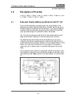
Page 19: ...or The 4 minute time stage prevents the timer from advancing to the next stage too early after switching on if the level switch has not reset The stainless steel drum body and its internal ribs serve as sensor contacts to monitor the residual moisture content of the load Once the required dryness level has been detected a control stage lasting 1 minute begins The timer will not advance to the next...

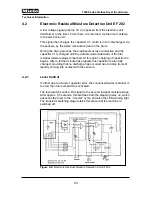
Page 20: ...isture stage is reached At this point charging of capacitor C2 begins After a further minute has elapsed this capacitor is also fully charged providing that no discharge has occurred due to damp items of laundry coming into contact with the sensors 4 2 1 Level Control If either due to a fault or operator error the condensed water container is too full then the level switch is activated The level s...

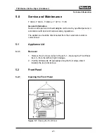
Page 21: ... local and national safety regulations The appliance should be disconnected from the mains before work is commenced 5 1 Appliance Lid 5 1 1 Removal 1 Remove the 2 screws refer to Figure 5 1 Opening the Front Panel Item 1 from the left and right lid edges 2 Pull the lid forwards lift up slightly along the front edge slide it towards the rear and remove 5 2 Front Panel 5 2 1 Opening the Front Panel ...

Page 22: ...t Panel 2 Remove the condensate container drawer to reveal 2 screws Item 2 and unscrew them 3 Remove the 4 screws Item 3 4 Open the air grid 5 Press the spring clip Item 4 down with the lid opener and open the front panel All components are easily accessible once the front panel has been opened 22 ...

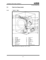
Page 23: ...3 Suppressor b3 Temp Selector Switch m1 Timer Motor b4 Temp Regulator m2 Drum Drive Motor b5 Temperature Limiter m3 Fan Motor b6 Temperature Limiter m4 Condensate Pump h0 Indicator Lamp P Timer h1 Buzzer r1 Heater Bank h2 Level Indicator Lamp u1 Electronic Unit k1 Capacitor for m2 u2 Residual Moisture Sensor Figure 5 2 Electrical Components T 368 C T 369 C 23 ...

Page 24: ...or Switch m1 1 Timer Motor b4 Temp Regulator m1 2 Timer Motor Reversing b5 Temperature Limiter m2 Drum Drive Motor b6 Temperature Limiter m3 Fan Motor h0 Indicator Lamp m4 Condensate Pump h1 Buzzer P Timer h2 Level Indicator Lamp r1 Heater Bank k1 Capacitor for m2 u1 Electronic Unit u2 Residual Moisture Sensor Figure 5 3 Electrical Components T 368 C from Machine no Prefix 11 24 ...

Page 25: ...k3 Suppressor b1 3 Door Contact Light C m1 1 Timer Motor Transport b2 Level Switch m1 2 Timer Motor Reversal b3 Temp Selector Switch m2 Drum Drive Motor b4 Temp Regulator m3 Fan Motor b5 Temp Limiter m4 Condensate Pump b6 Temp Limiter P Timer c1 Door Lock Relay r1 Heater Bank h0 Indicator Lamp u1 Electronic Unit h1 Buzzer u2 Residual Moisture Sensor h2 Level Indicator Lamp Figure 5 4 Electrical Co...

Page 26: ...ock B k3 Suppressor b1 3 Door Contact Light C m1 Timer Motor b2 Level Switch m2 Drum Drive Motor b4 Temp Regulator m3 Fan Motor b5 Temp Limiter m4 Condensate Pump b6 Temp Limiter P Timer d1 Relay Step Level r1 Heater Bank d2 Relay Cutout u1 Electronic Unit h1 Buzzer u2 Residual Moisture Sensor h2 Level Indicator Lamp h3 Drum Lighting Figure 5 5 Electrical Components T 377 C T 378 C 26 ...

Page 27: ... of the drum refer to Figure 5 6 Heater Bank Removal 1 Item 1 2 Unscrew the two screws in the central bearing refer to Figure 5 6 Heater Bank Removal 1 Item 2 3 Open the rear panel of the drum and lay it against the side Refer to Figure 5 7 Heater Bank Removal 2 4 Turn the retaining screws refer to Figure 5 7 Heater Bank Removal 2 Item 1 one turn to release the heater bank and remove it by pulling...

Page 28: ...nt to ensure that the bearing housing is correctly aligned at the position indicated by the arrow in Figure 5 7 and lightly screwed into place Then align a hole in the drum rear panel with one of the captive nuts insert a screw and tighten by hand Turn the drum by hand and fit all the other screws in the same way one by one then tighten them 28 ...

Page 29: ... 4 Turn the retaining screws refer to Figure 5 8 Heater Bank Removal Item 2 one turn to release the heater bank and remove it by pulling upwards 5 5 Heater Bank Thermostat 5 5 1 Replacement 1 Carry out the procedures described in Sections 5 4 1 or 5 4 2 depending on the type of the heater bank 2 Change the thermostat Note Until the following Machine nos if one thermostat should fail all units must...

Page 30: ...e 5 9 Fan Unit Removal 1 Item 1 3 Release the clip refer to Figure 5 9 Item 2 4 Remove the two screws on the vent duct refer to Figure 5 9 Item 3 5 Remove the exhaust vent duct by sliding it forward and down 6 Loosen the two screws refer to Figure 5 10 Fan Unit Removal 2 Item 1 by one turn 7 Remove the two screws refer to Figure 5 10 Item 2 8 Loosen the clip refer to Figure 5 10 Item 3 disconnect ...

Page 31: ...hen refitting the fan unit ensure that the wiring harness is correctly located in the retaining clip on the fan housing Also ensure that the connecting hose between the condensate pump and the collection vessel is laid and if necessary fixed so that it does not come into contact with the drum 31 ...

Page 32: ... 378 C Figure 5 11 Fan Unit with Drum Drive Motor Removal 1 Open the front panel 2 Remove the Plastic Plate refer to Figure 5 9 Fan Unit Removal 1 Note If the vent duct is mounted separately from the fill ring proceed as in Section 5 6 1 Fan Unit Removal Machine nos without Prefix Steps 3 5 3 Unscrew the fill ring and exhaust duct cover refer to Figure 5 11 Fan Unit with Drum Drive Motor Removal I...

Page 33: ...g screwdriver to slacken the drive belt as in Figure 5 12 and remove it from the drive pulley Figure 5 12 Removing the Drive Belt 5 Remove the two screws refer to Figure 5 13 Removing the Pump 6 Loosen the clip refer to Figure 5 13 Item 2 disconnect the hose and remove the pump Figure 5 13 Removing the Pump 33 ...

Page 34: ...r the U traverse Remove the unit Figure 5 14 Removing the Unit 5 7 Cooling Fan Circulation Fan Belt 5 7 1 Replacement 1 Open the front panel Refer to Section 5 2 1 2 Remove fill ring exhaust vent duct refer to Section 5 6 1 Fan Unit Removal Steps 2 5 3 With the left hand hold the belt on the pulley of the cooling fan 4 Turn the circulation fan by hand and ease the belt onto the circulation fan pul...

Page 35: ...r 5 6 2 3 Unscrew the knurled knobs refer to Figure 5 15 Condensate Pump Replacement Item 1 and lift out the pump complete with its cover 5 9 Microswitch 5 9 1 Replacement 1 Open the front panel Refer to Section 5 2 1 2 Remove the fan unit Refer to Section 5 6 1 or 5 6 2 3 Unscrew the knurled knobs refer to Figure 5 15 Condensate Pump Replacement Item 1 and lift out the pump complete with its cove...

Page 36: ...Removal 1 Open the front panel refer to Section 5 2 1 2 Remove the fan unit refer to Section 5 6 1 3 Unclip the spring refer to Figure 5 16 Drum Drive Motor Removal Item 1 and release the drive belt from the pulley 4 Remove the pivot bolt retainer refer to Figure 5 16 Item 2 5 Lift the motor slightly and withdraw the bolt 36 ...

Page 37: ...m motor Refer to Section 5 13 1 4 Remove the condensate pump if necessary Refer to Section 5 8 1 5 Release the spring refer to Figure 5 17 Cooling Fan Removal 1 Item 1 6 Remove the screws refer to Figure 5 17 Item 2 7 Turn the fan to the right refer to Figure 5 18 Cooling Fan Removal 2 and then tilt it to the front refer to Figure 5 19 Cooling Fan Removal 3 Note When refitting the fan ensure that ...

Page 38: ...Technical Information T300 Series Clothes Dryer Condenser Figure 5 18 Cooling Fan Removal 2 Machine Nos without Prefix Figure 5 19 Cooling Fan Removal 3 Machine Nos without Prefix 38 ...

Page 39: ...7 C 10 8341312 T 378 C Figure 5 20 Cooling Fan Removal Machine Nos with Prefix 10 or 11 1 Open the front panel Refer to Section 5 2 1 2 Remove the fan unit Refer to Section 5 6 1 3 Remove screws refer to Figure 5 20 Cooling Fan Removal Items 1 and 2 4 Remove the fan Note When refitting the fan ensure that the lower edge of the seal is correctly located and projects in the condenser box 39 ...

Page 40: ...elt 5 Unscrew the collector drawer frame refer to Figure 5 21 Drum Drive Belt Replacement 1 Item 2 and lay it with its hose connection in the condenser box 6 Cut through the damaged belt and remove it 7 Remove the screws refer to Figure 5 22 Drum Drive Belt Replacement 2 Item 1 and ease open the bearing ring panel 8 Slide the new belt through the gap between the bearing ring panel and the applianc...

Page 41: ...panel Figure 5 23 Drum Drive Belt Replacement 3 13 Remove the screws refer to Figure 5 23 Drum Drive Belt Replacement 3 Item 2 and ease open the bearing ring panel 14 Slide the new belt through the gap between the bearing ring panel and the appliance casing Refit the bearing ring panel and screw it tightly into place 15 Slide the belt into position on the drum and then onto the drive pulley 16 Rep...

Page 42: ...ard slightly out of its recess if built in Unscrew the fixing bracket refer to Figure 5 24 Drum Removal Item 1 and remove the inlet hose Remove the upper hinge piece refer to Figure 5 24 Item 2 and lift off the front panel 3 Carry out Steps 8 11 of Section 5 12 1 Drum Drive Belt Replacement 4 If the drum type is shown in Figure 5 25 Simple Folded Drum Edge see arrow slacken the bearing screws Figu...

Page 43: ...rew the two central bearing screws refer to Figure 5 6 Heater Bank Removal 1 Item 2 and remove the drum Figure 5 26 Rolled Drum Edge Note When re assembling the drum read the first paragraph of Section 5 4 1 Heater Bank Removal Machine Nos without a Prefix Note Adjust the support rollers refer to Figure 5 23 Drum Drive Belt Replacement 3 Items 3 and 4 in such a way as to ensure that the gap betwee...

Page 44: ...eps 2 5 or Section 5 6 2 Fan Unit Removal Machine Nos with Prefix Steps 2 and 3 3 Remove the bearing ring Refer to Section 5 12 1 Drum Drive Belt Replacement Steps 4 6 and 12 5 16 Bearing Shells 5 16 1 Replacement 1 Unscrew the drum rear panel Refer to Section 5 6 1 Fan Unit Removal Machine Nos without Prefix Steps 1 3 2 Lever off the upper section of the bearing shell with a screwdriver and remov...

Page 45: ...te Pump Replacement Item 1 3 Release the cooling pump spring refer to Figure 5 17 Cooling Fan Removal 1 4 Remove the screw below the condenser box and lift out the box Note When refitting ensure that the seal is first inserted recess down in the air duct before fitting the condenser box Also ensure that the lower edge of the seal from the cooling fan is correctly located and projects in the conden...

Page 46: ...te If the fill ring and duct are combined to form one piece remove the screws indicated in Figure 5 11 Fan Unit with Drum Drive Motor Removal then change the seal 2 Remove the vent duct refer to Section 5 6 1 Fan Unit Removal Machine Nos without Prefix Steps 3 5 3 Remove the 8 screws refer to Figure 5 27 Fill Ring Seal Replacement Item 1 and remove the fill ring 4 Replace the seal 46 ...

Page 47: ...r unit by unscrewing the 4 screws refer to Figure 5 28 Door Seal Replacement Item 1 2 Replace the seal 5 20 Outer Door Panel 5 20 1 Replacement 1 Turn the 6 tensioning levers refer to Figure 5 28 Door Seal Replacement Item 2 a quarter turn 2 Pull the bottom edge of the panel away from the inner door cap slightly and lift off towards the top 47 ...

Page 48: ... to Section 5 2 Front Panel The location of the module can be seen on the relevant Electrical Components figure in Section 5 3 5 21 2 Electronic Module EF 102 On a very few models in the initial production of the T 368 C machines the Roman numerals I IV were printed in reverse order This does not affect operation as all connections and plugs are coded and connected correctly 48 ...

Page 49: ...formation T300 Series Clothes Dryer Condenser 6 0 Fault Diagnosis T 368 C T 369 C T 369 C 2 T 377 C T 378 C 6 1 Checking the Sensor Controls T 377 C T 378 C Table 6 1 Checking the Sensor Controls T 377 C T 378 C 49 ...

Page 50: ...et service connection on the electronic unit 3 Connect the multimeter to the test module by plugging into the sockets near the rotary knob 4 Carry out tests according to the test chart Test Module Setting 1 Program Setting Selector Position Current EF 202 EF 202 from Part no 1752331 Extra Dry 2 2 µA Normal 10 2 µA Normal 11 14 0 018 mA Hand Iron 1 drop 18 0 44 mA Hand Iron 2 drops 21 22 1 50 mA Ma...

Page 51: ...Technical Information T300 Series Clothes Dryer Condenser 6 2 1 1 Test Chart Table 6 3 Test Chart 51 ...

Page 52: ...C with EPW 304 Prior to testing ensure that the address inputs are correct For measuring connect one magnetic lead to the rear panel and the other to one of the ribs Table 6 4 T 377 C T 378 C with EPW 304 Measuring device Elavi 5 Measured values in brackets refer to Metrawatt 52 ...

Page 53: ...it refer to Figure 6 1 Connecting the 7 Pole Plug Item 1 If necessary remove the electronic unit s top retaining screw Figure 6 1 Item 2 but ensure that the connections are not loosened Figure 6 1 Connecting the 7 Pole Plug 3 Connect a multimeter to the test module by plugging into the sockets near the rotary knob refer to Figure 6 2 Connecting a Multimeter 4 Refer to Table 6 5 Test Chart when car...

Page 54: ...l Information T300 Series Clothes Dryer Condenser Figure 6 3 Setting the Drying Program 5 When setting the drying program note that all voltages shown in the chart are only present at the positions indicated 54 ...

Page 55: ...l Information T300 Series Clothes Dryer Condenser 6 2 3 1 Test Chart Table 6 5 Test Chart Note In the Extra Dry program the timer skips to Normal and then switches onto Cooling Down after a maximum of 6 min 55 ...

Page 56: ...n as the level control closes the voltage changes with Elavi from approx 1 2 V to 3 6 V Metrawatt from approx 1 V to approx 15 V clear voltage jump recognizable If no voltage jump takes place check level control and cable connections 2 30 Drying time Following the voltage jump remove cable from measuring device Within a period of up to 3 min the lamp empty lights up and the timer skips to cool air...

Page 57: ...minutes to allow the correct air temperature to be reached and so that the thermostat in the fan starts operating Place the thermometer in the fluff filter recess in the door fastening it with adhesive tape if necessary and allow the appliance to run for a further 5 minutes Temperature Range Normal 90 100 C Low 84 94 C Table 6 7 Temperature Range Note On sensor controlled dryers even with the temp...

Page 58: ...r seal between the rear of the heat exchanger and the condenser box Fault Rectified From Machine no 6867167 Remedy Fit new seal Part no 1290482 Note The seal must be fitted so as to ensure that the seal lips face towards the heat exchanger 6 4 3 Connecting Hose Condensate Pump Possible Cause Unprotected hose worn through by abrasive action from the drum as its wire retainer is missing Fault Rectif...

Page 59: ...ontainer with drip edge Part no 1670212 6 4 5 At Outlet Connection Possible Cause The non return valve does not seal correctly Fault Rectified From Machine no 9066712 Remedy Replace complete outlet connection Part no 1670181 6 5 Noises 6 5 1 At the Sensor Brushes Especially when Running Counterclockwise Possible Cause Weak spring does not give sufficient pressure Fault Rectified From Machine no 69...

Page 60: ...ine no 6769295 Right bearing Part No 1641982 From Machine no 6769296 Left Right Bearing Part No 1482841 Table 6 8 Replacement Bearing Part Numbers 6 6 Laundry is Not Dried 6 6 1 Inoperative Heating Possible Cause Thermostat failure Fault Rectified From Machine Nos 7633263 T 368 C 7650601 T 377 C 7632736 T 369 C 7642779 T 378 C Remedy If there is a thermostat failure on a model with Machine no prio...

Page 61: ... Instruction 12 7 8 6 7 Water Container Drawer 6 7 1 Drawer Cannot be Fully Closed Possible Cause The container spout snap closure is too strongly sprung and does not open sufficiently to allow the drawer to close Fault Rectified From Water container Part no 1653361 Remedy Fit a weaker spring Part no 1670291 6 7 2 Water Container Does Not Locate Correctly When Pushed In and Opens Again Possible Ca...

Page 62: ...8 Dryer Fails to Operate 6 8 1 Control Lamp Lights Up But Dryer Fails to Operate Possible Cause Relay door safety relay damaged or charred Fault Rectified From Machine no 9587769 Condenser dryer From Machine no 9597965 Vented dryer T 369 C from Machine no 8399820 until 9542308 Relays without plug housing used Remedy On appliances prior to the above listed Machine nos the plug housing and connector...

Page 63: ...red to Spares Depts Have had this resistor added either retrospectively or during production In this case there is no resistor integrated in the wiring harness Electronic module EF 201 with protective resistor has Part no 1752311 Electronic module EF 202 with protective resistor has Part no 1752331 Electronic modules with this additional resistor can be used with wiring harnesses where it is also ...

Page 64: ...ld be removed and not replaced If during any service work on a washing machine or a tumble dryer it is noted that an interference suppressor with this Part no is fitted then to avoid possible faults occurring it should be removed 6 10 Loud Running Noises at Drum Brushes Possible Cause Loud noises caused by the brushes rubbing on the drum slip rings Fault Rectified Modified brush unit has been fitt...

Reviews: