background image

ALARMS AND EVENTS LIST 


REV.0.03_COD.610078_A4 

Page  42 


12.


ALARMS AND EVENTS LIST 

12.1


Description of alarm messages 

During machine operation, the user is aided by 

ALARMS

 or 

ALARM MESSAGES

 which 

make use of visual signals on the operator display panel to advise of possible anomalies in 
progress and machine alarms which have intervened. 

Intervention of an ALARM during operation of the system is signaled to the user by a 
message on the operator panel.  

The alarm which appears on the panel remains active until the cause of intervention is 
removed. 

The intervention of an alarm stops the wash cycle currently in progress. 


12.2


List of alarm messages 

Possible alarms which may intervene during a work cycle are shown on the control panel 
display. 

The message includes the number of the alarm that has intervened and its name. 

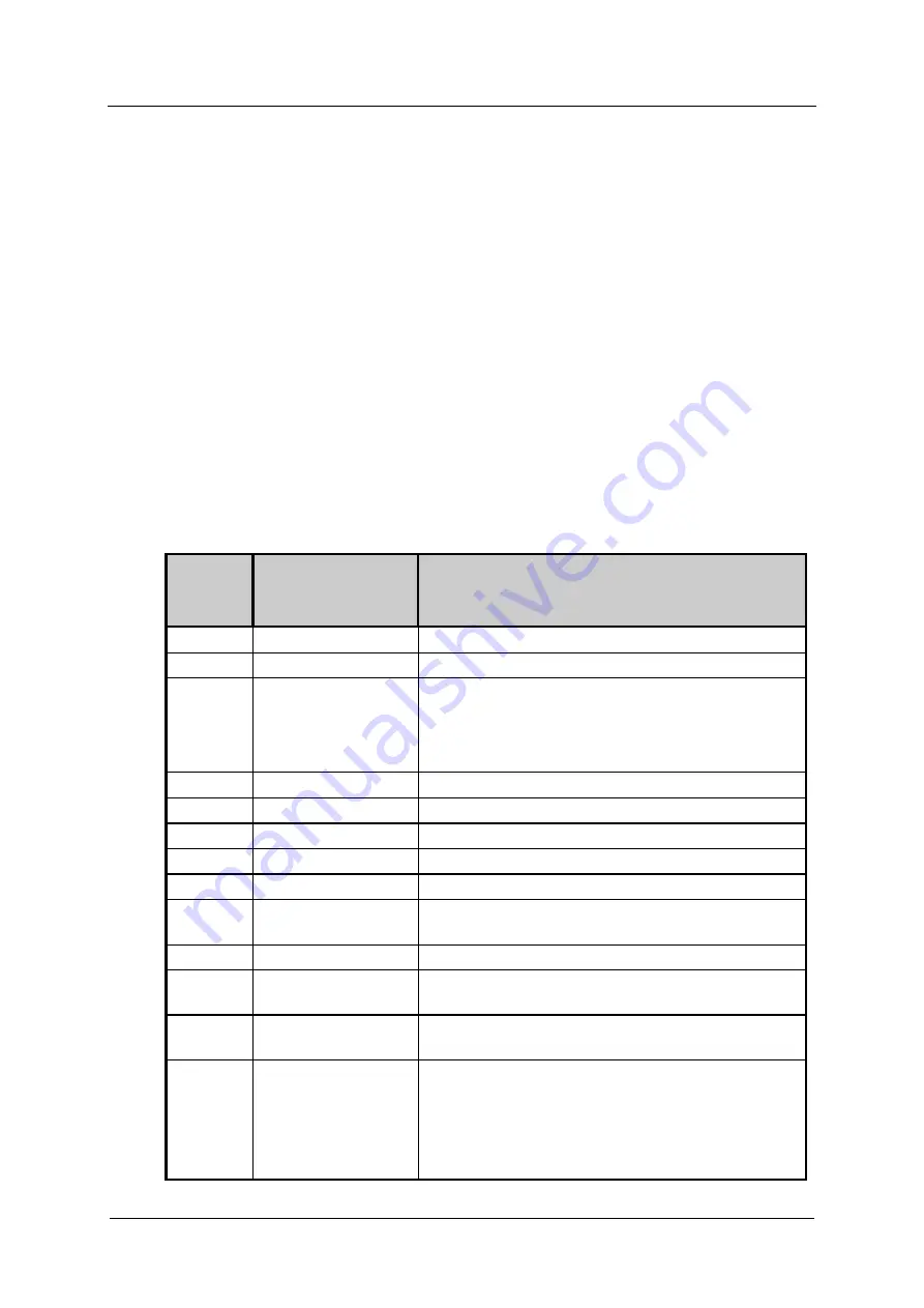
A complete list of possible alarm messages follows. 


ALARM 

DISPLAY 
MESSAGE 

DESCRIPTION 

E 2 

open load. door 

Door open and/or unlocked during cycle. 

E 4 

load.door fail. 

Door blocked but open (discrepancy). 

E 7 

unblock.door 1 

Door problems: 


Overtime lock door. 


During block door, the door has been 
opened.  

E 9 

unlocking 1fail. 

Overtime unlock door. 

E11 no 

cold 

water  Timeout 

cold water filling level 

E12 

no hot water 

Timeout hot water filling level 

E13 

no demin. water 

Timeout demineralized water filling level 

E23 

drain problem 

Timeout minimum water level during the drain. 

E26 prewash 

max°C 

Chamber temperature exceeded selected value 
during pre-wash. 

E27 

tank probe lim°C 

Chamber temperature above maximum value. 

E30 tank 

probe 

Temperature sensor defective - Operation sensor 
(sensor 1) 

E31 

tank probe 2 

Defective temperature sensor - Redundant sensor 
(sensor 2)  

E34 check 

temp. 

Appears when all the following conditions are met: 


Chamber temperature above selected value. 


Temperature difference between the two 
probes is greater than 35.6°F (2°C). 


Chamber heating failure. 

Summary of Contents for 62850501USA

Page 1: ...id the risk of accidents or damage to the machine it is essential to read these instructions before it is installed and used for the first time en US Operating Instruction LABORATORY GLASSWARE WASHER PLW 8505 ...

Page 2: ...raining 13 User profiles 13 3 INSTALLATION 14 3 1 Water connection 14 Inlet water quality 14 Information 15 3 2 Electrical connection 16 3 3 Adding and dispensing cleaning agents 17 Presence sensor of cleaning agent 17 3 4 Replacement or refill of cleaning agent 17 3 5 Warning 18 3 6 Connecting the drain hose 19 Drain cooling 20 3 7 Ambient ventilation requirements 20 4 CHECKS PRIOR TO START UP 21...

Page 3: ...4 Date and time setting 38 9 5 Selecting a language 38 9 6 Changing user name 39 9 7 Parameter overview 40 10 CLOCK 41 11 HISTORICAL DATA 41 12 ALARMS AND EVENTS LIST 42 12 1 Description of alarm messages 42 12 2 List of alarm messages 42 12 3 List of warning messages 43 13 USB PORT 43 14 MAINTENANCE 44 14 1 General recommendations on maintenance 44 Machine status 44 14 2 Maintenance request 44 14...

Page 4: ...GENERAL RULES REV 0 03_COD 610078_A4 Page 4 16 TECHNICAL DATA 53 17 DISPOSING OF YOUR OLD MACHINE 55 ...

Page 5: ...re subsequently placed on the market do not oblige the manufacturer to intervene on previously supplied machines nor to consider the machine and the related user s manual lacking and inadequate The installation maintenance and operating instructions given in the following pages have been prepared to ensure the long life and outstanding performance of the appliance The instructions in this manual d...

Page 6: ...4 Page 6 2 PRODUCT INFORMATION Before starting work the user must be completely familiar with the functions and proper operation of the machine The user must know the precise function of all command and control devices of the machine PLW 8505 ...

Page 7: ...s such as test tubes beakers flasks cylinders etc Measuring vessels such as measuring cylinders volumetric flasks etc Dishes such as petri dishes watch glasses etc Small items such as lids spatulas magnetic stirring rods stoppers etc Other items such as funnels Laboratory glassware and laboratory utensils for cleaning are referred to as the wash load if they are not more specifically defined Proce...

Page 8: ...ed for use in commercial environments Some metal parts pose a risk of injury being cut Wear cut resistant protective gloves when transporting and setting up the machine If the machine is built under it must only be installed under a continuous countertop which is firmly secured to adjacent units to improve stability The electrical safety of this machine can only be guaranteed when correctly ground...

Page 9: ...e or near vicinity with a water hose or a pressure washer The machine must be disconnected from the power supply before any maintenance or repair work is carried out Quality assurance The following points should be observed to assist in maintaining quality standards when processing laboratory glassware and utensils to avoid damage to the loads being cleaned If it is necessary to interrupt a progra...

Page 10: ...over nets or place in a mesh tray for small items so that they do not block the spray arms Empty any containers or utensils before loading them The amount of residual solvents and acids on items going into the cabinet should be minimal There should be no more than a trace of any solvents with a flash point of below 70 F 21 C Ensure that solutions or steam containing chlorides or hydrochloric acid ...

Page 11: ...selves in Then make appropriate arrangements for its safe disposal Safety signal used To inform personnel operating on the machines of obligations of behavior and residual risks adequate safety signals as set forth by 92 58 EEC are applied to the machine and near the workplace GENERIC SAFETY SIGNALS In particular labels with signals of obligation prohibition and danger contained in this manual and...

Page 12: ...was designed for use with water and cleaning agents Do not use organic or other types of solvents as this may result in the risk of explosion or the rapid deterioration of certain machine parts Acids particularly hydrochloric acid can damage steel Contact should be avoided Use original accessories only Never use powder detergents Never use foaming detergent Accessories which are not approved by th...

Page 13: ...peration and maintenance of the system user profiles are identified as follows SERVICE Installation and repair technican ADMIN Responsible authority for the machine in the workplace More advanced tasks e g interrupting or canceling a program require more detailed knowledge about the machine cleaning of laboratory glassware and laboratory untensils Alterations or adaptations of the lab washer e g a...

Page 14: ...exceeds 100 mg l the risk of corrosion to items being cleaned in the lab washer will be further increased In certain regions e g mountainous areas the water composition may cause precipitates to form requiring the use of softened water in the steam condenser The lab washer is supplied as standard for connection to cold water blue coded and hot water up to max 140 F red coded Connect the inlet hose...

Page 15: ...ding to IEC61770 If the connection of hot and cold water is not available the two corresponding supply pipes must be connected together The manufacturer declines all responsibility for damage or injury caused by improper installation If you do not comply with the conditions above the deriving damages will not warranty ATTENTION When the machine is not in operation always close the water valves ...

Page 16: ...hat the electrical systems are efficiently grounded The ground conductor is to be connected to the ground terminal identified by the standard symbol The machine is equipped with a terminal identified by the relative symbol for equipotential connections between appliances see rules for electrical plants Connect the machine and the relative dedicated disconnection device not supplied by using a powe...

Page 17: ...ng procedure Have a new container with cleaning agents ready Take the empty container Remove the siphon and place it on a chemical resistant and easy to clean surface Insert the siphon into the new container Wipe up any spillages Place the cleaning agent container in the area for the storage of chemical substances Venting Dosing System by execute the Fill DOS1 program for detergent or Fill DOS2 pr...

Page 18: ...cleaning agents only Do not use powder detergent Always follow the relevant manufacturer s instructions on storage and disposal of cleaning agents Check that the type of cleaning agents is suitable for the specific washing program used ATTENTION Before undertaking any sort of movement of the machine ensure the machine is completely drained of any residual water chemical residues and cleaning agent...

Page 19: ... and ring nut Tighten the ring nut firmly Insert the drain hose and clamp it in place Insert the other end of the hose into the drain unit installing it properly and locking it in position It is necessary to follow these instructions for drain connection Drain hose must be connected by using a clamp Drain hose must not present angles or irregular curving in its course Drain point must be placed at...

Page 20: ...prepare an air conditioning or air circulation system capable to balance the emissions reported in the installation plan Only when toxic detergents are used and or it is expected that it is not possible to guarantee acceptable levels of temperature and humidity in the installation environment the air exhaust of the equipment must be connected to a venting system The air that is expelled from the c...

Page 21: ...tage Check the efficiency of the emergency and machine shutdown devices circuit breaker Check the efficiency of the door opening safety microswitch Check the operation of machine controls especially the START and STOP commands 4 3 General controls Indicative list of general adjustments and checks to be made Check proper execution of general supplies of the machine electrical and plumbing Ensure th...

Page 22: ...rritating corrosive or toxic ingredients Prior to use carefully read the safety information provided by the cleaning agent supplier and the label applied to the package 5 2 Opening and closing the door Pull on handle to open door The glass door is insulated however it may be hot Use caution when opening not to touch it ATTENTION Keep hold of the door during opening and closing Jerking the door ope...

Page 23: ...is a risk of burning scalding or chemical burns If a program is cancelled the items in the lab washer must be cleaned again 1 An emergency release device is located above the door labelled accordingly 2 Insert the tool into the emergency release opening 3 Keep pushing the tool In this moment the door is unlocked and it is possible to open it 4 To close the door keep pushing the tool as described a...

Page 24: ...ake apart any items which can be dismantled according to the manufacturer s instructions and process the individual parts separately from each other Do not place items to be cleaned inside other pieces where they may be concealed Do not place items so close together that cleaning is hampered Arrange the load so that water can access all surfaces Only clean small items and micro components in speci...

Page 25: ...the point in which it had been stopped Two presses for canceling a program The machine returns to the stand by condition and the door is unlocked cancel For canceling a process B START Starting a program confirm For selecting or confirming entries in the user interface C P For accessing the list of all additional programs D PRG The menu incorporates all relevant functions During standby Press the ...

Page 26: ...A0 value 5 Target temperature for current program phase 6 Remaining time 7 Warning message 8 Cycle counter 9 Temperature in chamber Sensor 2 with A0 value At the beginning while the machine is in the stand by status it displays the type of program selected temperature date and time By pressing one of the program button P1 P2 or P3 the display shows the program associated to the key and at the left...

Page 27: ... By pressing PRG button twice a screen with alarms and warnings is displayed Pic 3 PIC 4 In case of an error a window appears indicating the identification alarm code and a brief description as shown in Pic 4 In case of failure which does not lead to a block such as lack of chemical a message is shown at the left bottom of the screen Pic 1 point 7 or by pressing twice the PRG button as shown in Pi...

Page 28: ... interrupted a window appears with a message warning the disinfection lack Pic 6 A In case of cycles without desinfection this window appears by pressing STOP only once Pic 6 B If the temperature in a cancelled program was 149 F 65 C or lower the message shown in Fig 6 A is displayed If the temperature was above 149 F 65 C the message shown in Fig 6 B is displayed ...

Page 29: ...eratures between 113 F 45 C and 149 F 65 C with the addition of appropriate cleaning agent Interim rinse In the interim rinse stages the cleaning agents from the previous wash blocks are rinsed off and neutralized where necessary by the addition of appropriate neutralizing agents Final rinse To avoid deposits and corrosion on the load demineralized AD water should preferably be used if available f...

Page 30: ... HW 1 Min DI 1 Min HW 1 Min Wash Neutrali zation 2 Wash Neutrali zation 1 Interim rinse 1 HW DOS2 2 Min HW DOS2 3 Min HW DOS2 2 Min HW DOS2 1 Min HW DOS2 2 Min Wash Main wash 2 HW DOS1 158 F 70 C 3 Min Wash Main wash 1 HW DOS1 122 F 50 C 3 Min HW DOS1 140 F 60 C 3 Min HW DOS1 140 F 60 C 3 Min HW DOS1 149 F 65 C 3 Min HW DOS1 131 F 55 C 3 Min Wash Pre wash 2 Wash Pre wash 1 CW 2 Min CW 2 Min CW 2 M...

Page 31: ...ash Interim rinse 2 HW 1 Min DI 1 Min Wash Neutrali zation 2 Wash Neutrali zation 1 Interim rinse 1 DI DOS2 1 Min HW DOS2 1 Min HW DOS2 1 Min Wash Main wash 2 Wash Main wash 1 DI DOS1 194 F 90 C 3 Min HW DOS1 122 F 50 C 3 Min HW DOS1 149 F 65 C 3 Min Wash Pre wash 2 Wash Pre wash 1 CW 5 Min CW 2 Min CW 2 Min Block Function Button Program Microbiol Prewash Customer specific 1 Customer specific 2 ...

Page 32: ... Customizable programs with pre set vaules to be adjusted Wash Final rinse 2 Wash Final rinse 1 Wash Interim rinse 4 Wash Interim rinse 3 Wash Interim rinse 2 Wash Neutrali zation 2 Wash Neutrali zation 1 Interim rinse 1 HW 10 s HW 10 s HW 10 s Wash Main wash 2 Wash Main wash 1 HW DOS1 10 s HW DOS2 10 s HW DOS 3 10 s Wash Pre wash 2 Wash Pre wash 1 Block Function Button Program Fill DOS1 Fill DOS2...

Page 33: ...PROGRAMS REV 0 03_COD 610078_A4 Page 33 7 3 Start the program In order to start follow the procedure as described below Select a program Press START button ...

Page 34: ... machine is ready for operation and the door is closed it is possible to press the START button 8 2 Program status The cycle performs a defined series of program stages The user interface displays the current program stage in progress and the temperature in the chamber The display indicates that the door is open as appropriate or it issues warning messages e g lack of chemicals 8 3 Power failure I...

Page 35: ...d as follows Press the STOP and START buttons together and keep pressed for 5 seconds Press the program P2 button followed by the program P1 button The machine is reset and returns to ready for operation and it s possible to open the door Note If the machine shutdown persists due to a fault in one of its components e g faulty probe etc the door is released and the machine remains inactive In case ...

Page 36: ...assword allow the access to all menus but with limited modification possibility If the password is lost contact Miele Service or an authorized service technician 9 1 Accessing the menu To access the menu keep the PRG button pressed for 5 seconds Press the P1 and P2 buttons to scroll through the menu Press START button to confirm selection Press STOP button to exit the menu and return to Ready for ...

Page 37: ...t be confirmed by pressing STOP The error message window then disappears 9 3 Buzzer volume setting Hold PRG pressed for 5 seconds Use buttons P1 and P2 to scroll through the menu to the following options Each value must be confirmed individually by pressing START Setting Parameter Entering password System Select one of the following parameters using buttons P1 and P2 o Parameter 1 07 Keypad tone v...

Page 38: ...dually by pressing START Exit the menu by pressing STOP 9 5 Selecting a language Use the following parameters to select the display output language Hold PRG pressed for 5 seconds Use buttons P1 and P2 to scroll through the menu to the following options Each value must be confirmed individually by pressing START Setting Parameter Entering password System Select one of the following parameters using...

Page 39: ...pressing START Setting Parameter Entering password System Select the following parameters using buttons P1 and P2 o Parameter 1 01 User name selection Confirm selection by pressing START Use buttons P1 and P2 to select a user and press START to confirm User names can consist of up to 16 characters Each character must be selected individually with buttons P1 and P2 and confirmed by pressing START A...

Page 40: ...T 1 05 Printout of results of current cycle 0 disabled 1 enabled 0 1 SEL KEYBOARD 1 07 Buzzer volume loading side 0 buzzer switched off 0 50 NUM KEYBOARD 1 08 Buzzer volume end of cycle 0 50 NUM KEYBOARD 1 09 Buzzer alarm volume 0 buzzer switched off 0 50 NUM KEYBOARD 1 13 Show A0 value in display 0 disabled 1 enabled 0 1 SEL KEYBOARD 1 16 Historical cycles memory full 0 no warning 1 warning 2 war...

Page 41: ...3 05 Standard 140 F 60 C 180 seconds 01 When 95 of the memory is full the dump memory message appears on the display To deactivate the recurring message follow the steps below Hold PRG pressed for 5 seconds Use buttons P1 and P2 to scroll through the menu to the following options Each value must be confirmed individually by pressing START Setting Parameter Entering password System Select one of th...

Page 42: ... list of possible alarm messages follows ALARM DISPLAY MESSAGE DESCRIPTION E 2 open load door Door open and or unlocked during cycle E 4 load door fail Door blocked but open discrepancy E 7 unblock door 1 Door problems Overtime lock door During block door the door has been opened E 9 unlocking 1fail Overtime unlock door E11 no cold water Timeout cold water filling level E12 no hot water Timeout ho...

Page 43: ...exceeded in main wash 12 3 List of warning messages DISPLAY MESSAGE DESCRIPTION press start It is possible to start a cycle during a stand by state no chemical 1 The cleaning agent associated to dosing pump 1 is used up Diagnostics with dosing pump enabled Pressure switch state with pressure switch presence no chemical 2 The cleaning agent associated to dosing pump 2 is use up Diagnostics with dos...

Page 44: ...fter a specified time or after a specified number of working hours This warning does not affect the normal use of the machine 14 3 Routine maintenance Routine maintenance includes all the operations aimed at keeping various parts of the machine clean and functional It must be performed on a regular basis or when it is considered necessary due to incorrect performance of a washing cycle Since these...

Page 45: ...t forth in the table and in accordiance to the daily routine controls check list It is however advisable to carry out single cleaning tasks anytime you feel they may be necessary WARNING Never clean the machine or and its immediate surrounding area with a water hose or a pressure washer CLEANING THE EXTERNAL BODY OF THE MACHINE Operator USER Frequency once a day METHOD OF CLEANING EXTERNAL BODY Us...

Page 46: ... every day METHOD OF INTERVENTION Clean the washing chamber drain filters in the following manner Open the washing chamber door and remove the basket Warning Hot surface Remove the drain water filtering assembly from the chamber Unscrew the threaded pin and remove the cover of the drain water filter basket ...

Page 47: ...various washing cycles Remove and clean any deposits and incrustations from the washing chamber drain Place back the clean filter on the washing chamber drain Put the cover for the drain water filter back in place Lock it in position with the threaded pin Put the drain water filter group back in the wash chamber ...

Page 48: ...ERVENTION Clean the washing chamber thermostat probe in the following manner Open the wash chamber door and remove the basket Visually check the washing chamber thermostat probe If deposits or lime incrustations can be seen clean thermostat probe using a damp cloth and an appropriate detergent Take care not to damage or move the probe ...

Page 49: ...wo rotors and remove them from the chamber Unscrew the closure plug of the rear part of the nozzle and remove it Carefully clean and remove any incrustations from the washing rotor nozzles using appropriate detergents Put the plugs back in place at the ends of the spray arms Make sure the gasket is properly positioned and in good condition Replace it if necessary Put the rotors back in the machine...

Page 50: ...ecial maintenance tasks Cleaning and checking operations Frequency Action Operator Special maintenance tasks must be carried out by Miele Service after 1000 operating hours or every 12 months Water solenoid filters Check clean and in case replace them Maintenance of dosing systems Temperature probes Safety thermostat sensor verfication Water solenoid valves Check for any leakage Drain pump Check f...

Page 51: ...eplace as necessary C No detergent in tank R Turn the machine off and fill the tank P MACHINE DOES NOT REACH SET TEMPERATURE FOR THE SELECTED WASHING CYCLE C The thermostat probe of the washing chamber is dirty or covered with lime R Clean the thermostat probe of the washing chamber performing the routine maintenance described in MAINTENANCE chapter of this manual P MACHINE DOES NOT PROPERLY RUN W...

Page 52: ...age 52 P DETERGENT FILLING PHASE DOES NOT OCCUR CORRECTLY C Chemical dispensing pump is not working properly R Perform the routine maintenance set forth in MAINTENANCE chapter of this manual C Chemical dispensing pump failed R Contact Miele Service ...

Page 53: ...pm CaCO3 7 f Max conductivity ph n a 7 8 pH n a 7 8 pH WARM WATER Connection male DN 20 Max flow rate 3 2 gpm 12 lt min Min flow pressure 14 5 PSI g 100 kPa Max pressure 116 PSI g 800 kPa Max temperature 140 F 60 C Max hardness 70 ppm CaCO3 7 f Max conductivity ph n a 7 8 pH n a 7 8 pH DEMI WATER Connection male DN 20 Max flow rate 3 2 gpm 12 lt min Min flow pressure 14 5 PSI g 100 kPa Max pressur...

Page 54: ...on working 264 lb 120 daN kg Floor load 3559 lb ft 15 daN m kg m Foot support area 2 8 in 18 cmq HEAT EMISSIONS Max from frames 1126 BTU 330 W Max from trolley 122 F 1194 BTU 350 W Overvoltage category according to IEC EN 60664 rule II UL mark 61010 1 Certifications CAN CSA C22 2 No 61010 1 04 CAN CSA C22 2 No 61010 2 040 UL Std No 61010 1 2nd Edition IEC 61010 2 040 2006 Manufacturer address Stee...

Page 55: ...ntain specific materials compounds and components which were essential for their correct function and safety These could be hazardous to human health and to the environment if disposed of with your domestic waste or if handled incorrectly Please do not therefore dispose of your old appliance with your household waste Please dispose of it at your local community waste collection recycling center fo...

Page 56: ...vice Alteration rights reserved Publication date 2019 11 26 U S A Miele Inc National Headquarters 9 Independence Way Princeton NJ 08540 Phone 800 991 9380 Fax 609 419 4241 www miele pro com proinfo mieleusa com Technical Service Support Phone 800 991 9380 Fax 800 220 1348 proservice mieleusa com ...

Reviews: