background image


STEP 4 

Now that the drive plate and wide drive rings have been removed, place a 
3/16” collet into the collet holder.  Insert the tip of the spindle, just above 
the fork, into the collet.  Once the collet is tightened, use a flat head 
screwdriver to unscrew the spindle bolt.  Then pull the various pieces 
apart and place on your work surface. 


STEP 5 

You can now place the nose piece in a 13/32” collet.  Unscrew the sheath 
housing from it while simultaneously depressing the latch.  This will 
keep the flange on the nose piece from being caught up. 


STEP 6 


If you need to replace the latch on the sheath housing, place it over two 
v-blocks.  Hold a small punch or pin with a set of tweezers over one end 
of the pin in the housing.  Gently tap the pin out of the housing and 

remove the latch and spring.  The replacement latch kit is part# 40503.  
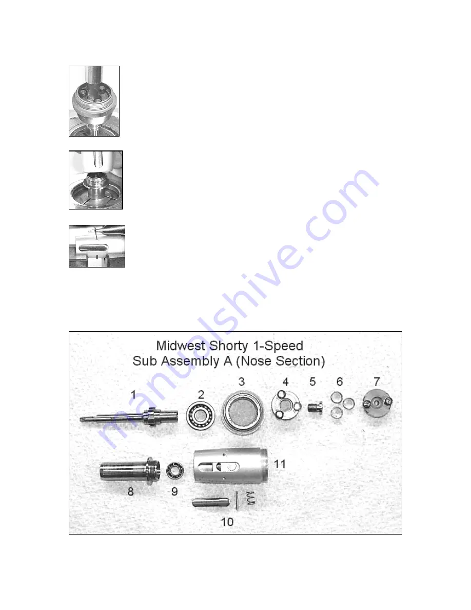


STEP 7 

You can now place the component parts in your ultrasonic cleaner.  After you clean the 
parts, align them like the exploded view below and replace what is needed. 


Summary of Contents for Shorty Single Speed Motor

Page 1: ...Tru Torc and Shorty troubleshooting guide immediately preceding this section Sub Assembly A B Disassembly STEP 1 Remove the front sheath housing Do this by placing it in a 3 4 collet All the threads...

Page 2: ...screw the sheath housing from it while simultaneously depressing the latch This will keep the flange on the nose piece from being caught up STEP 6 If you need to replace the latch on the sheath housin...

Page 3: ...de of the motor housing You will need to use your 035 allan wrench 20115A Once again unscrew the screw in a counterclockwise fashion STEP 9 After you remove the screw take the drive ring retainer out...

Page 4: ...from the raceway Use your Lares assembly tool 00024L2 to punch the bearing out of the raceway Always replace these motor bearings when performing an overhaul Place all of your dirty or fouled parts i...

Page 5: ...punch press the spindle into the impeller STEP 17 If you did not replace the rear o ring and vent plug in STEP 11 do so now STEP 18 Place the rear turbine bearing 40405C into Hole 2 of your work block...

Page 6: ...ol as shown Grooves are pre cut into the tool and will properly space the wide drive rings STEP 25 With the drive rings properly placed in the drive ring tool lower the partially assembled nose sectio...

Page 7: ...start this step over Forcing Sub Assembly A and B will cause the LocTite to be broken loose on the turbine STEP 27 To firmly tighten the two assemblies together once again place the sheath housing in...

Reviews: