background image

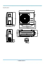
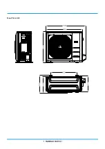
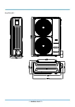
 Outdoor Unit 5 

Panel Plate CA30

Summary of Contents for MUEU-18HRFNX-QRD0W

Page 1: ...LIGHT COMMERCIAL INVERTER SERIES SM_LC GA _R410A_R32_3D INV_EU_NA_1811 SERVICE MANUAL...

Page 2: ......

Page 3: ...ce Indoor Unit 1 Indoor Unit Compact Four way Cassette Type 2 Indoor Unit A6 Duct Type 3 Indoor Unit Floor Ceiling Type Outdoor Unit 1 Dimensional Drawings 2 Service Space 3 Capacity Correction Factor...

Page 4: ...e by Error Code 7 Troubleshooting by Error Code 8 Check Procedures Indoor Unit Disassembly 1 Indoor Unit Compact Four way Cassette Type 2 Indoor Unit A6 Duct Type 3 Indoor Unit Floor Ceiling Type Outd...

Page 5: ......

Page 6: ...Contents 1 Precautions 2 2 Information servicing For flammable materials 3 Safety Precautions...

Page 7: ...d perform electri cal work For more information contact your dealer seller or an authorized service center CAUTION While unpacking be careful of sharp edges around the unit as well as the edges of the...

Page 8: ...work taking place the area around the equipment is to be surveyed to make sure that there are no flammable hazards or ignition risks NO SMOKING signs shall be displayed 2 7 Ventilated area Ensure tha...

Page 9: ...on of refrigerant in the atmosphere from a leak 2 12 Cabling Check that cabling will not be subject to wear corrosion excessive pressure vibration sharp edges or any other adverse environmental effect...

Page 10: ...use of reclaimed refrigerant It is essential that electrical power is available before the task is commenced Become familiar with the equipment and its operation Isolate system electrically Before at...

Page 11: ...iated electrical components are sealed to prevent ignition in the event of a refrigerant release Consult manufacturer if in doubt The recovered refrigerant shall be returned to the refrigerant supplie...

Page 12: ...Contents 1 Model Reference 2 2 External Appearance 3 Model Reference...

Page 13: ...purchased equipment Indoor Unit Model Universal Outdoor Unit Model Capacity Btu h Power Supply Cassette MCA3U 18HRFNX QRD0W MOB30 18HFN1 QRD0W 18k 1 220 240V 50Hz A6 Duct MTIU 18HWFNX QRD0W Floor Cei...

Page 14: ...Model Reference 3 2 External Appearance 2 1 Indoor Unit Compact Four way Cassette A6 Duct Floor Ceiling...

Page 15: ...Model Reference 4 2 2 Outdoor Unit Outdoor Unit...

Page 16: ...s 4 3 Part names 5 4 Service Place 6 5 Accessories 7 6 Air Velocity and Temperature Distributions 8 7 Capacity Tables 12 8 Noise Criterion Curves 18 9 Electrical Characteristics 20 10 Electrical Wirin...

Page 17: ...l box adopts new design which can meet higher fire safety requirements 1 3 Reserved remote on off and alarm ports Optional for fixed speed units standard for inverter units Remote on off With the rese...

Page 18: ...frared remote controller wired controller can be fixed on the wall and avoid mislaying It s mainly used for commercial zone and makes air conditioner control more convenient 1 7 Louver Position Memory...

Page 19: ...IDU Compact Cassette 4 2 Dimensional Drawings...

Page 20: ...IDU Compact Cassette 5 3 Part names Drain pump within indoor unit Drain pipe Air outlet Air inlet Display panel Front grille Louver Refrigerant pipe...

Page 21: ...IDU Compact Cassette 6 4 Service Place...

Page 22: ...Outlet pipe clasp some models 1 Drain joint some models 1 Seal ring some models 1 EMC Magnetic Ring some models Magnetic ring wrap the electric wires S1 S2 P Q E around the magnetic ring twice 1 Magn...

Page 23: ...IDU Compact Cassette 8 6 Air Velocity and Temperature Distributions 18K Discharge Angle 30 Cooling airflow velocity distributions Cooling temperature distributions...

Page 24: ...IDU Compact Cassette 9 Heating airflow velocity distributions Heating temperature distributions...

Page 25: ...IDU Compact Cassette 10 Discharge Angle 60 Cooling airflow velocity distributions Cooling temperature distributions...

Page 26: ...IDU Compact Cassette 11 Heating airflow velocity distributions Heating temperature distributions...

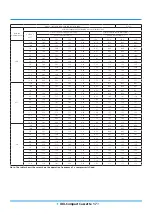
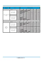
Page 27: ...4 5 74 5 74 5 79 5 79 5 79 5 79 6 19 6 19 6 19 6 19 S T 0 69 0 76 0 83 0 89 0 57 0 63 0 70 0 76 0 51 0 58 0 64 0 70 0 38 0 44 0 50 0 56 PI 1 14 1 14 1 14 1 14 1 14 1 14 1 14 1 14 1 14 1 14 1 14 1 14 1...

Page 28: ...12 2 12 2 14 2 14 2 14 2 14 720 15 TC 5 74 5 74 5 80 5 86 6 05 6 05 6 05 6 05 6 20 6 20 6 20 6 20 6 57 6 57 6 57 6 57 S T 0 70 0 78 1 00 1 00 0 56 0 64 0 72 0 98 0 49 0 57 0 66 0 73 0 35 0 42 0 49 0...

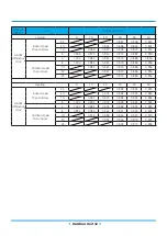
Page 29: ...4 11 4 11 4 11 4 45 4 45 4 45 4 45 S T 0 74 0 84 0 94 1 00 0 59 0 68 0 77 0 86 0 52 0 61 0 69 0 78 0 36 0 44 0 52 0 60 PI 2 16 2 16 2 16 2 16 2 17 2 17 2 17 2 17 2 18 2 18 2 18 2 18 2 20 2 20 2 20 2...

Page 30: ...23 1 23 1 23 1 23 1 23 1 23 20 TC 5 48 5 48 5 53 5 59 5 82 5 82 5 82 5 82 5 99 5 99 5 99 5 99 6 42 6 42 6 42 6 42 S T 0 72 0 81 0 90 0 98 0 58 0 66 0 75 0 83 0 51 0 59 0 68 0 76 0 36 0 44 0 51 0 59 P...

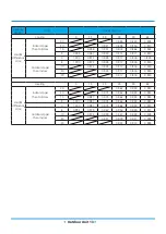
Page 31: ...1 73 1 79 1 76 1 78 7 0 4 63 4 60 4 57 4 54 1 84 1 90 1 87 1 89 5 6 4 67 4 64 4 61 4 59 1 80 1 82 1 83 1 84 2 8 4 70 4 64 4 64 4 61 1 72 1 73 1 74 1 75 0 0 4 67 4 61 4 59 4 56 1 64 1 65 1 65 1 66 2 8...

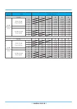
Page 32: ...84 0 89 0 91 7 0 5 77 5 71 5 68 5 65 0 88 0 89 0 95 0 97 5 6 5 60 5 54 5 51 5 48 0 91 0 96 0 99 1 01 2 8 5 40 5 37 5 34 5 31 0 99 1 04 1 07 1 10 0 0 5 16 5 11 5 08 5 08 1 06 1 12 1 14 1 17 2 8 5 11 5...

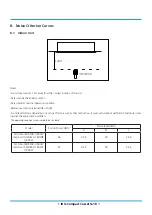
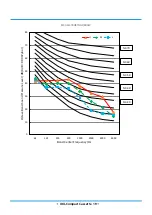
Page 33: ...rence acoustic pressure OdB 20 Pa Sound level will vary depending on a range of factors such as theconstruction acousticabsorptioncoefficient ofparticular room in which the equipment is installed The...

Page 34: ...act Cassette 19 MCA3U 18HRFNX QRD0W 0 10 20 30 40 50 60 70 80 63 125 250 500 1000 2000 4000 8000 Octave Band Sound Pressure Level dB 0dB 0 0002 bar Band Center Frequency Hz H M L NC 70 NC 60 NC 50 NC...

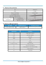
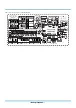
Page 35: ...2 5 Strong Electric Signal 4 1 0 4 2 5 with auxiliary electric heater Weak Electric Signal 10 Electrical Wiring Diagrams IDU Model IDU Wiring Diagram Field Wiring Diagram MCA3U 18HRFNX QRD0W 160225000...

Page 36: ...To CCM Comm Bus CN7 T2B OUTER PIPE TEMP POWER P1 CN3 JR6 JR6 FAN1 CAP1 Y G P3 P2 6 CN4 2 H CH P4 Y G 4 BROWN BLACK CN110 YELLOW Y G TO OUTDOOR UNIT P5 MAGNETIC RING MAGNETIC RING NOTE The wiring diag...

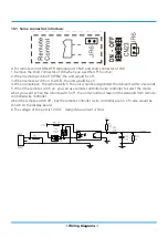
Page 37: ...on 4 When close open the remote switch the unit would be responded the demand within 2 seconds 5 When the remote switch on you can use remote controller wire controller to select the mode what you wan...

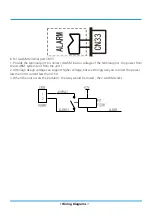
Page 38: ...ut no voltage of the terminal port the power from the ALARM system not from the unit 2 Although design voltage can support higher voltage but we strongly ask you connect the power less than 24V curren...

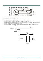
Page 39: ...tput voltage is the power supply 3 The fresh motor can not excess 200W or 1A follow the smaller one 4 The new fresh motor will be worked when the indoor fan motor work when the indoor fan mo tor stops...

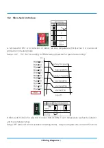
Page 40: ...i cold wind action in heating mode Range 24o C 15o C 8o C According to EEROM setting reserved for special customizing B Micro switch SW2 is for selection of indoor FAN ACTION if room temperature reach...

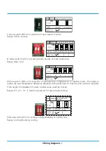
Page 41: ...r selection of temperature compensation in heating mode This helps to reduce the real temperature difference between ceiling and floor so that the unit could run properly If the height of installation...

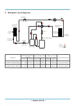
Page 42: ...nts 1 Dimensional Drawings 2 2 Service Place 9 3 Capacity Correction Factor for Height Difference 10 4 Noise Criterion Curves 16 5 Refrigerant Cycle Diagrams 18 6 Electrical Wiring Diagrams 19 Outdoor...

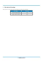
Page 43: ...Outdoor Unit 2 1 Dimensional Drawings Please check the corresponding dimensional drawing according to the panel plate ODU Model Panel Plate MOB30 18HFN8 QRD0W B30 MOB30 18HFN1 QRD0W B30...

Page 44: ...Outdoor Unit 3 Panel Plate B30...

Page 45: ...Outdoor Unit 4 Panel Plate BA30...

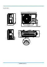
Page 46: ...Outdoor Unit 5 Panel Plate CA30...

Page 47: ...Outdoor Unit 6 Panel Plate D30...

Page 48: ...Outdoor Unit 7 Panel Plate E30...

Page 49: ...Outdoor Unit 8 Panel Plate 590...

Page 50: ...Outdoor Unit 9 2 Service Place...

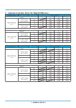
Page 51: ...970 0 1 000 0 993 0 978 0 970 Outdoor Upper than Indoor 5 0 992 0 985 0 970 0 962 10 0 977 0 962 0 955 Capacity Btu h 18k Pipe Length m Cooling 5 10 20 30 Height difference H m Indoor Upper than Outd...

Page 52: ...ndoor 5 1 000 0 989 0 968 0 947 0 926 0 905 10 0 989 0 968 0 947 0 926 0 905 20 0 968 0 947 0 926 0 905 25 0 947 0 926 0 905 Heating 5 10 20 30 40 50 Height difference H m Indoor Upper than Outdoor 25...

Page 53: ...ndoor 5 1 000 0 984 0 951 0 919 0 886 0 854 10 0 984 0 951 0 919 0 886 0 854 20 0 951 0 919 0 886 0 854 25 0 919 0 886 0 854 Heating 5 10 20 30 40 50 Height difference H m Indoor Upper than Outdoor 25...

Page 54: ...ndoor 5 1 000 0 972 0 945 0 917 0 876 0 834 10 0 972 0 945 0 917 0 876 0 834 20 0 945 0 917 0 876 0 834 30 0 917 0 876 0 834 Heating 5 15 25 35 50 65 Height difference H m Indoor Upper than Outdoor 30...

Page 55: ...ndoor 5 1 000 0 971 0 941 0 912 0 868 0 824 10 0 971 0 941 0 912 0 868 0 824 20 0 941 0 912 0 868 0 824 30 0 912 0 868 0 824 Heating 5 15 25 35 50 65 Height difference H m Indoor Upper than Outdoor 30...

Page 56: ...ndoor 5 1 000 0 966 0 931 0 897 0 846 0 794 10 0 966 0 931 0 897 0 846 0 794 20 0 931 0 897 0 846 0 794 30 0 897 0 846 0 794 Heating 5 15 25 35 50 65 Height difference H m Indoor Upper than Outdoor 30...

Page 57: ...valid at nominal operation condition Reference acoustic pressure OdB 20 Pa Sound level will vary depending on arrange off actors such as the construction acoustic absorption coefficient of particular...

Page 58: ...Octave Band Sound Pressure Level dB 0dB 0 0002 bar Band Center Frequency Hz Cooling Heating NC 70 NC 60 NC 50 NC 40 NC 30 NC 20 0 10 20 30 40 50 60 70 80 63 125 250 500 1000 2000 4000 8000 Octave Band...

Page 59: ...e Diameter mm inch Piping length m ft Elevation m ft Additional Refrigerant Gas Liquid Rated Max Rated Max MOB30 18HFN8 QRD0W 12 7 1 2 6 35 1 4 5 16 4 30 98 4 0 20 65 6 12g m 0 13oz ft MOB30 18HFN1 QR...

Page 60: ...Outdoor Unit 19 6 Electrical Wiring Diagrams ODU Model ODU Wiring Diagram ODU Main Printed Circuit Board MOB30 18HFN8 QRD0W 16022000031449 17122000002718 MOB30 18HFN1 QRD0W...

Page 61: ...R UNIT S 2 N L N RED BLUE OR BLACK 1 L Y G AMBIENT TEMP SENSOR DISCHARGE TEMP SENSOR CN 21 CONDENSER TEMP SENSOR Y G COMPRESSOR U V W BLUE RED BLACK BLUE RED WHITE CN 25 MAIN BOARD CN 1A CN 3 CN 1 CN...

Page 62: ...Outdoor unit printed circuit board diagram 17122000002718...

Page 63: ...pipe temp sensor T3 ambient temp sensor T4 exhaust temp sensor TP 8 TP T4 T3 CN21 connect to pipe temp sensor T3 ambient temp sensor T4 exhaust temp sensor TP 9 PMV CN31 connect to Electric Expansion...

Page 64: ...Installation 4 Outdoor Unit Installation 5 Drainage Pipe Installation 6 Refrigerant Pipe Installation 7 Vacuum Drying and Leakage Checking 8 Additional Refrigerant Charge 9 Engineering of Insulation...

Page 65: ...3 MC MC 4 5 6 7 8 Install the indoor unit Install the outdoor unit Install the drainpipe Connect the wires Connect the refrigerant pipes Evacuate the refrigeration system Install the panel only for c...

Page 66: ...minimum distance between the outdoor unit and walls described in the installation guide does not apply to airtight rooms Be sure to keep the unit unobstructed in at least two of the three directions M...

Page 67: ...nel dimensions 4 Refrigerant piping 5 Suspension bolt 4 6 Ceiling opening dimensions 7 Hanger bracket 8 Ceiling board 2 Drill 4 holes 5cm 2 deep at the ceiling hook positions in the internal ceiling B...

Page 68: ...e embedded in advance Make sure that the hooks do not come loose due to concrete shrinkage After installing the indoor unit fasten the installation paper template onto the unit with bolts M6X12 to det...

Page 69: ...the buckles at the back of the grille be properly seated in the groove of the panel 3 3 4 Connect the two wires of the panel to the main board of the unit 3 3 5 Fasten the control box lid with two scr...

Page 70: ...ll as indoor and outdoor wires with their connection points before mounting the unit 5 Drill 4 holes 10cm 4 deep at the ceiling hook positions in the internal ceiling Be sure to hold the drill at a 90...

Page 71: ...uce noise if the end user requires 3 4 Adjust the air inlet direction From rear side to under side 1 Take off ventilation panel and flange Air return flange Ventilation panel 2 Change the mounting pos...

Page 72: ...the cut was made and consolidate the roof beam 2 After the selection of the installation location position the refrigerant pipes drain pipes and indoor and out door wires to the connection points befo...

Page 73: ...side Wall Mounted Installation 8 Mount the indoor unit onto the hanging screw bolts with a block Position the indoor unit on a flat level by using a level to prevent leaks Screw nut Washer Hanging scr...

Page 74: ...75 4 3 Install Outdoor Unit Fix the outdoor unit with anchor bolts M10 60cm 23 6 Fix with bolts Caution Since the gravity center of the unit is not at its physical center so please be careful when lif...

Page 75: ...ng table is for reference PVC pipe Reference value of inner diameter of pipe mm Allowable maximum water flowrate l h Remark Slope 1 50 Slope 1 100 PVC25 20 39 27 For branch pipe PVC32 25 70 50 PVC40 3...

Page 76: ...The length of lifting pipe should not exceed 750mm 29 5in The drainage pipe should be set down inclined after the lifting pipe immediately to avoid wrong operation of water level switch Refer the fol...

Page 77: ...he maximum permissive length is based on the system reliability 2 Oil traps If the indoor unit is installed higher than the outdoor unit If oil flows back into the outdoor unit s compressor this might...

Page 78: ...over or adhesive tape to avoid duct or exog enous impurity come into the pipe 7 Drill holes if the pipes need to pass the wall 8 According to the field condition to bend the pipes so that it can pass...

Page 79: ...r 1 5 hours of drying check whether there is leakage source 4 Leakage test After the vacuum degree reaches 755mmHg stop vacuum drying and keep the pressure for 1 hour If the indicator of vacuum gauge...

Page 80: ...arging The air in the flexible pipe and manifold gauge should be exhausted After finished refrigerant recharge process check whether there is refrigerant leakage at the connec tion joint part Using ga...

Page 81: ...Electrical Wring 1 Highlights of electrical wiring installation All field wiring construction should be finished by qualified electrician Air conditioning equipment should be grounded ac cording to th...

Page 82: ...lowing points Indoor unit Whether the switch on the remote controller works well Whether the buttons on the remote controller works well Whether the air flow louver moves normally Whether the room tem...

Reviews: