


FRONT PANEL DESCRIPTION
Power Switch: On/off switch to turn UPS on and off.
Power on indicator: Indicates the UPS is turned on.
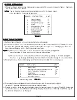
LCD display: The LCD display indicates a variety of UPS operational conditions (see page 15 for LCD
display definitions).
LCD display toggle button: Toggles between a variety of UPS operational conditions (see page 15).
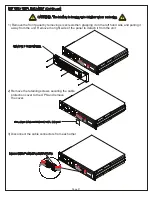
REAR PANEL DESCRIPTION
Non-Critical Load Circuit Breaker: Circuit output resettable circuit breaker. Provides overload protection.
7
Junction Box Cover: Remove to access wiring for critical and non-critical output circuits. Circuit wiring is
labeled accordingly. (See page 10 for output wiring instructions)
Non-Critical Load Receptacle: Non-Critical load receptacle, NEMA 5-20R.
Critical Load Circuit Breaker: Critical circuit output resettable circuit breaker. Provides overload protection.
Expansion Port: Slot for Network Interface Card (NIC). Part Number UPS-IPCARD.
6
5
9
10
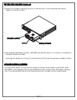
USB Port: Connects UPS to your computer via the supplied USB cable for UPS setup, configuration and
unattended shutdown in the event of a power failure. For use with the supplied Middle Atlantic Power
Manager software. (Please Note: The USB and Serial ports cannot be used simultaneously)
11
4
3
2
1
1
2
3
4
External Battery Pack Connector: Use to connect the optional MAP external battery pack
(Part No. UPS-EBPR) for extended UPS runtime. A maximum of ten (10) battery packs can
be daisy-chained together.
5
6
7
8
9
10
11
8
Page 7
WIRE COLOR AND FUNCTION
LINE
RED
BLACK
CRITICAL
LOAD
NON-CRITICAL
LOAD
GROUND
GREEN
GREEN
NEUTRAL
WHITE
WHITE
Input:
48V
Expansion Port
E325394
6G48
Primary
Secondary
Serial Port
IN
OUT
125V
16A
60Hz
1650W
2150VA
Wiring Fault
Reset
EPO
D
A
T
A
Non-Critical Load
125VAC
60Hz - 16A
Reset
Non-Critical Load
Reset
Critical Load
125VAC
60Hz - 16A