EQUIPMENT ACCESS
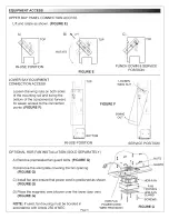
UPPER BAY PANEL CONNECTION ACCESS
Lift and rotate as shown.
(FIGURE E)
A)
B) \
l i f t
TOP
ROTATE
C)
TOP
TOP
IN-USE POSITION
FIGURE E
PUNCH DOWN & SERVICE
POSITION
LOWER BAY EQUIPMENT
CONNECTION ACCESS
Loosen the wing nuts on both sides
of the mounting rail and swing the
bottom of the component(s) forward
for easier access to the connection
points.
(FIGURE F)
TOP
LOOSEN
WING NUT
FIGURE F
SWING
OUT
BOTTOM
IN-USE POSITION
SERVICE POSITION
OPTIONAL HDR-FAN INSTALLATION (SOLD SEPARATELY)
A) Remove preinstalled fan guard bolts.
(FIGURE G)
B) Remove the solid plate covering the fan opening.
(FIGURE G)
C) Install fan and ensure that power cord is positioned as shown.
(FIGURE G)
D) Place the magnetic vent blocker over the lower door vent.
(FIGURE G)
NUTS
GUARD
NOTE:
If used, fan housing must be bonded in
accordance with Article 250 of NEC
Page 5
HDR-FAN
POWER CORD
WIRE PROVISION
HDR-FAN
FAN
HOUSING
" K — -HDR-FAN
GUARD
I '^ ^ S C R E W S
FIGURE G


