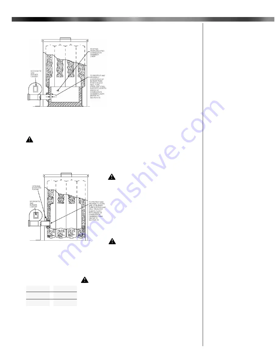
A combustion chamber liner is normally required to protect non-heat transfer surfaces and to
provide a radiant bed for rapid heat transfer to the primary surfaces of the heat exchanger. In
most cases, the oil burner combustion chamber
liner formerly used can be used, if in good condi-
tion.
In the case of wet base boilers, where the
entire combustion chamber is comprised of heat
exchange surfaces and no combustion chamber
liner was provided for oil firing, a liner is usually
not required for the ECONOMITE. However, a
liner or target wall may be necessary if the com-
bustion chamber is unusually short, in order to
avoid flame contact on the heat exchanger walls
or flueways.
If a built up chamber liner is required, use
2300°F minimum insulating material.
The burner tube, or the stainless steel sleeve
that is included with the burner, must be sealed
air tight into the combustion chamber liner open-
ing with refractory material as shown by Figures
1,2 and 7. The sleeve is preferred as it is
designed to properly locate the end of the tube relative to the inside wall of the combustion
chamber, and to permit burner removal without breaking the seal.
CAUTION:
In no case should the burner tube be allowed to extend into the cham-
ber proper; it must be set at least 1" short of the inside surface , because high combus-
tion chamber temperatures will cause premature thermocouple and pilot deterioration.
Special heat resistant alloy extension tubes and instructions are available for those applica-
tions where the burner tube is too short to reach the combustion chamber (such as old-fash-
ioned gravity warm air furnace installations).
WARNING: Burner cabinet must be
mounted in orientation shown in figures 1
and 2. Any other mountings may cause a
dangerous condition, and will void burner
warranty and agency approvals. Non-
standard arrangements may be available
for some models; consult factory for
details if required.
Before permanently setting the burner in place,
check venturi casting openings and pilot assem-
bly to make sure they are free of foreign materi-
als. See Figure 8.
WARNING: The chimney shall be
inspected for unsafe conditions such as
deteriorated masonry and excessive soot
or other blockage or potential blockage.. Installation must conform with local
codes or in the absence of local codes with ANSI Z21.8 latest edition and NFPA,
ANSI Z223.1 latest edition.
WARNING: The Vent Connector shall not be con-
nected to a chimney already venting solid fuel burning
appliances, an incinerator or an open fireplace.
The Vent Connector shall be made of non-combustible, corro-
sion resistant material capable of withstanding the vent gas tem-
perature produced by the gas utilization equipment and of suffi-
cient thickness to withstand physical damage.
The Vent Connector shall be as short as possible. The
entire length shall be readily accessible for inspection, cleaning and replacement.
The length of horizontal uninsulated Vent Connector between chimney and a single gas uti-
lization equipment shall not exceed 75% of the height of the chimney above the connector, or
100% if the Vent Connector is insulated.
3
III Combustion Chamber
IV Chimney, Vent
Connector*,
and Draft Control
*Formerly referred to as Flue Pipe
Figure 1:
Dry Base Boiler with Combustion
Chamber Liner (Warm Air Furnace
Construction is Similar)
Figure 2:
Wet Base Boiler with
Combustion Chamber Unlined
Maximum
Firing Rate
Vent
Connector
250 MBH
320 MBH
400 MBH
7"
8"
9"
Table 1: Recommended
Vent Connector Sizes


