DX-2200
– SD/HD-SDI Text & Graphics Inserter – User Manual
Page 61 of 103
Command
Code
Mode of Operation
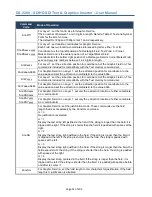
LnnnPM2
Set the position coordinates for the layer n to be specified as center position of the
overlay.
nnn is the layer number(s), See **
** The layer number nnn is a 1 to 3 digit number specifying one or more layers:
n = 0
– Apply to all Layers (Graphics Layer 1, Graphics Layer 2, Graphics Layer 3)
n = 1
– Graphics Layer 1
n = 2
– Graphics Layer 2
n = 3
– Graphics Layer 3
4.8.1.13 User Interface Commands
The user interface commands control the behavior of the DX-2200-TI and allow reconfiguration of the
functions performed by the DIP switch and toggle switch to customize the product for specific applications.
Configuration of the switches consists of two steps. The switch(s) to be configured are assigned to a user
interface function, and the user interface function is programmed to perform the required operations.
The DX-2200-TI has 4 DIP switches and one momentary contact toggle switch that toggles both left and
right. Different commands are used to assign the DIP and toggle switches.
4.8.1.13.1 DIP
S
WITCH
A
SSIGNMENTS
DIP Switch Assignments DIP switches are assigned to user interface functions using the ‘US’ commands.
An assignment command example is US1:01. This command will assign DIP Switch #1 to control user
interface function 01.
One or more DIP Switches can be assigned to the same user interface function. The number of switches
assigned determines how many different operations can be selected from the user interface function. When
one switch is assigned, two operations are available. Two switches allow four operations, three switches
allow eight operations and four switches allow the selection of 16 operations.
The factory default settings for the Toggle Switch are listed in Table 23: Operation of 2-Position Momentary
Toggle Switch and for the DIP Switch, Table 24: Operation of the 4-Position DIP Switch.
4.8.1.13.2 T
OGGLE
S
WITCH
A
SSIGNMENTS
Toggle switch supports two functions: a toggle right or a toggle left function which are assigned using the UR
and UL commands respectively. The assignments can apply either to all modes of operation, or to one
specific mode. For example command: UR:03 will set toggling the Toggle Switch to the right to control user
interface function 03.
4.8.1.13.3 U
SER
I
NTERFACE
F
UNCTION
C
ONFIGURATION
The user interface functions are software components that have a selection input that is controlled by the
physical Switches that are assigned to it. For each value of the selection input, a different Serial Command
string can be assigned.
The DX-2200-TI has 20 user interface functions numbered 01 through 20. Each user interface function
supports up to 16 selections that are numbered 00 to 15. In the factory default configuration, all user
interface functions are unused and have no commands assigned to them.
The switches that control a user interface function can be either one or more DIP Switches, or a Toggle
Switch.
Summary of Contents for DX-2200
Page 87: ...DX 2200 SD HD SDI Text Graphics Inserter User Manual Page 87 of 103 ...
Page 92: ...DX 2200 SD HD SDI Text Graphics Inserter User Manual Page 92 of 103 ...
Page 97: ...DX 2200 SD HD SDI Text Graphics Inserter User Manual Page 97 of 103 ...
Page 100: ......
Page 101: ......
Page 102: ......
Page 103: ......

