2
• Audio-visual material may include works of copyright which must NOT be recorded without the authority of the
owner of copyright.
• Note that voltage is supplied to the unit whenever the plug is connected to the supply socket.
• Clock display on the front panel is a indication that the main power is on.
• Keep the unit away from radiators or other sources of heat.
• Do not spill liquid of any kind onto the unit. If liquid is accidently spilled onto the unit, immediately remove the
mains plug from the supply socket, and consult a qualified service engineer.
•
MOISTURE CONDENSATION:
If you pour a cold liquid into a glass, water vapor in the air will condense on the
surface of the glass. This is moisture condensation. Moisture condensation on the head drum, one of the most
crucial parts of the video recorder, will cause damage to the tape. Whenever the video recorder is exposed to
extreme cold and heat at the same time, some condensation will occur. When moisture is present, turn the power
switch on, and allow at least 2 hours for the video recorder to dry out.
• Use the video recorder in a horizontal (flat) position only.
• Before operating, remove any paper wrapping which may have been affixed to the recorder during manufacture. DO
NOT COVER VENTILATION OPENINGS ON TOP AND SIDES OF THE RECORDER DURING OPERATION.
• When a cassette is inserted into the loading compartment, the power is switched on automatically as long as the
power cord is plugged into an AC outlet. DO NOT force a cassette into the compartment when the power cord is
unplugged.
• Keep the recorder and video cassette away from strong magnetic fields.
• After playing a video casssette, remove it from the recorder.
DO NOT move the recorder with a cassette in the compartment.
• Store video cassettes in their sleeve or case and position them vertically.
• If a cassette has been subjected to cold temperature, allow it to warm to room temperature before recording or
playback.
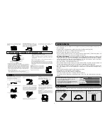
Carefully remove the VCR from the carton. Check to see that the VCR has not been damaged. The following
accessories are included.
IMPORTANT NOTES
ACCESSORIES
No other DAEWOO VCR has the same serial numbers as
yours. You will find the serial number and model
number on the rear of your VCR.
Make sure both numbers are recorded here so that you
will have them in case your VCR is stolen or you need a
complete description for identification.
Model No.
Serial Number
Purchase Date:
Purchased From:
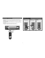
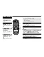
1. Wireless remote control
NOTE:
Required 2 "AAA" batteries
TV/VCR
MENU
CLEAR
DISPLA
Y
EJECT
CH/TRK
SLOW/SHT
SPEED
CM SKIP
AT
R
3S
END
ST
ART
1
2
3
4
5
6
7
8
9
100
INPUT
PLA
Y
REW
REC/OTR
FF
ST
OP
P/S
0
POWER
DV-T572A
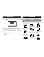
–Never place the set in a confined space such as a
bookcase, or built-in cabinet, unless proper ventilation
is provided.
Power-Cord Protection
–Route the power cord so
that it is not likely to be walked on or pinched by
items placed upon or against them, paying particular
attention to the plugs, receptacles, and the point
where the cord exits from the appliance.
–Do not place the set near over a radiator or heat
register, or where it is exposed to direct sunlight.
SERVICE
Damage Requiring Service
–Unplug the set from
the wall outlet and refer servicing to qualified service
personnel under the following conditions:
–When the power cord or plug is damaged or frayed.
–If liquid has been spilled or objects have fallen into
the set.
–If the set has been exposed to rain or water.
–If the set has been dropped or the cabinet has been
damaged.
–If the set does not operate normally by following the
operating instructions. Adjust only those controls that
are specified in the operating instructions. Improper
adjustment of other controls may result in damage
and will often require extensive work by a qualified
technician to restore the set to its normal operation.
–When the set exhibits a distinct change in
performance–this indicates a need for service.
Servicing
–Do not attempt to service the set yourself
as opening or removing covers may expose you to
dangerous voltage or other hazards.
Refer all servicing to qualified service personnel.
Replacement parts
–When replacement parts are
required, be sure the service technician has used
replacement parts specified by the manufacturer that
have the same charac-teristics as the original parts.
Unauthorized substitutions may result in fire, electric
shock, or other hazards.
Safety Check
–Upon completion of any service or
repairs to the set, ask the service technician to
perform routine safety checks (as specified by the
manufacturer) to determine that the set is in safe
operating condition.
OUTSIDE ANTENNA, EQUIPMENT, AND POWER EXPOSURE
1. ENSURE SAFE ANTENNA AND CABLE CONNECTIONS
If an outside antenna or cable system is connected to the set, be sure the antenna
or cable system is grounded so as to provide some protection against built up
static charges and voltage surges. Section 810 of the National Electrical Code.
ANSI/NEPA No. 70-1984, provides information with respect to proper grounding
of the mast and supporting structure, grounding of the lead-in wire to an antenna
discharge unit, size of grounding conductors, location of antenna discharge unit,
connection to grounding electrodes and requirements for the grounding electrode:
See figure 1 for items a-d below.
a. Use No. 10 AWG (5.3mm
2
) aluminum. No. 8 AWG (8.4mm
2
) No. 17-AWG
(10mm
2
) copper-clad steel or bronze wire, or larger, as ground wire.
b. Secure antenna lead-in and ground wires to house with stand-off insulators
spaced from 4 feet (1.22m) to 6 feet (1.83m) apart.
c. Mount antenna discharge unit as close as possible to where lead-in enters
house.
d. Use jumper wire not smaller than No. 6 AWG (13.3mm
2
) copper, or the
equivalent, when a separate antenna grounding electrode is used. See NEC
Section 810-21 (I).
2. ELIMINATE ANTENNA PROXIMITY TO HIGH VOLTAGE POWER SOURCES OR
CHANCE OF ACCIDENTAL CONTACT BY INSTALLER
An outside antenna system should be located where it will never be reached by
power lines, electric light or power circuits and where it will never contact these
power sources if it falls. Installer should use extreme care to avoid possible fatal
contact by touching power lines, circuits or other power sources when installing
outside antenna.
Lightning
–For added protection for this set during a
lightning storm, or when it is left unattended and
unused for long periods of time, unplug it from the
wall outlet and disconnect the antenna or cable
system. This will prevent damage to the set due to
lightning and power-line surges.
FRAYED OR CUT
AC LINE
CRACKED PLUG
SERVICE DEPT
ALL SETS RECEIVE
OUR OK
SAFETY CHECK.
2. Coaxial cable for connecting
the VCR to your TV's VHF terminal.
3. BATTERY
"Attential because of the transportation,
battery could be discharged."


