


Rotary Microtome HM 325
MICROM International GmbH
Robert-Bosch-Str. 49
D- 69190 Walldorf
387821 - English
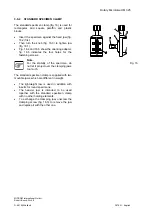
3-10-2 DISPOSABLE BLADE CARRIER E
Inserting the blade:
•
The disposable blade carrier E is designed to
take all commercially available high and low
profile blades.
•
Insert the blade 20.5).
•
When using high profile blades, first loosen
the two screws (fig. 20.9) and remove the
spacer strip (fig. 20.3).
•
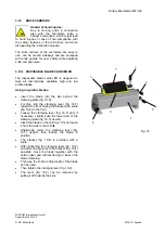
Turn the clamping lever (fig. 20.7) to the front.
•
Swing the bracket with scale (fig. 20.4) to the
front.
•
Loosen the clamping lever (fig. 20.7) and, if
necessary, slightly press the lower part of the
clamping plate as well.
•
A small gap between rail (fig. 20.3) and
clamping plate (fig. 20.5) can be seen.
•
Insert the blade on the rail (fig. 20.3) and push
it from the side to the middle.
•
Afterwards, return the clamping lever (fig.
20.7) upright, thus locking the blade in
position.
•
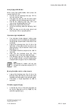
The bracket (fig. 20.4) is provided with a
scale.
•
After loosening the clamping lever (fig. 20.7)
and after having moved the bracket (fig. 20.4)
upwards, move the blade together with
clamping plate (fig. 20.5) according to the
scale by means of the knife guard to the left or
right side.
•
This way, the entire cutting length of the blade
can be used. Then press the clamping lever
(fig. 20.7) upwards.
•
The levers (fig. 20.7 and 20.3) can be
removed by pulling them off towards the side.
•
The lever (fig. 20.7) can also be used on the
left side. This way, the blade can be clamped
with the left hand.
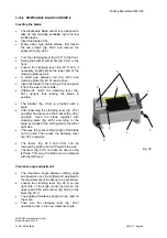
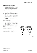
Clearance angle adjustment:
•
The clearance angle between cutting edge
and specimen can be shifted and adjusted to
the requirements of the tissue to be sectioned.
•
Loosen the clamping lever (fig. 20.3) on the
right side of the knife carrier and move the
upper part of the knife carrier (fig. 20.2) on the
base (fig. 20.1).
•
The adjusted clearance angle can be read on
the scale.
•
Then turn the clamping lever (fig. 20.3)
upwards to lock in the new clearance angle.
Fig. 20
1
2
3
4
5
6
7
8


