background image

microHAM © 2016  All rights reserved

Configuring microHAM USB Device Router 


The MicroHAM USB Device Router (Router) program provides a Windows compatible configuration tool for 
microHAM USB Devices (USB Interface II as well as microKEYER, CW Keyer and USB Interfaces) and 
software interface to other Windows applications (loggers, digital mode software, etc.).  The software 
interface is provided as Virtual Serial Ports.

To configure and use USB Interface II with Windows compatible application programs it is necessary to 
have installed the USB driver, started the Router, and applied power to USB Interface II by turning on the 
attached radio or external power supply.  Router is then configured to match the requirements of the 
application (logger or digital mode) software. 


USB Interface II Status


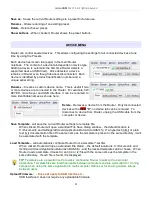
When the USB driver is installed correctly Router will show a 
device tab with a   GREEN check beside the device name (USB 
Interface II).  The yellow POWER LED must also be ON for USB II
to operate properly.  DO NOT proceed with setup unless you have 
both a green check and  the yellow POWER LED is ON.  


Creating and Using Virtual Serial Ports


microHAM Router provides a set of virtual serial ports which allow Windows applications (loggers and digital
software) to work with USB Interface II just as they would work with "real" (hardware) serial ports. 

In order to use these virtual Ports, you must first create the ports and then assign  a function (radio control, 
PTT, CW, FSK, etc.) to each virtual port. 

DO NOT define a port that is already in use (for example, COM1 or COM2 which are hardware ports on 

many motherboards) or a virtual port used by another USB device.  
Router will not allow using a COM port number which is already 
present in the system but ports are sometimes hdden.  If a another 
device which also uses virtual serial ports (external USB devices, 
bluetooth devices, PDA etc ...) is not connected to the computer when
creating virtual ports in Router, the ports can overlap and will not work
properly when you connect such device.    

IMPORTANT WARNING: Before creating virtual COM 
ports, attach all external devices you will use with the 
computer.  Restart Router and then create the virtual 
COM ports.

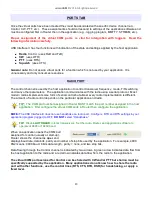
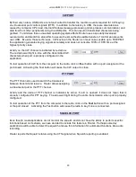
Virtual ports are created from
the Virtual Port menu.  

Create - Creates virtual COM
ports. It is possible to select

more than one port at a time by holding the Ctrl key and
clicking several port numbers. Creating virtual ports may take a while,  be patient.

7

Summary of Contents for USB Interface II

Page 1: ...microHAM 2016 All rights reserved USB Interface II microHAM fax 421 2 4594 5100 e mail support microham com homepage www microham com Version 8 0 1 March 2016 1...

Page 2: ...uter 6 Creating and Using Virtual Ports 6 5 microHAM DEVICE ROUTER 9 Menu Router 9 Menu Preset 10 Menu Device 11 Menu Virtual Port 12 Menu Help 12 Ports Tab 13 Radio Port 13 CW Port 14 PTT Port 14 Squ...

Page 3: ...ports Icom Kenwood TenTec Yaesu and other radios no separate level converter required Squelch input for additional software control Strong RFI immunity integrated chokes and filters for best RFI immun...

Page 4: ...B15F connector for radio interconnection a detailed description is in Appendix A 4 USB USB B connector for computer connection Connect a standard USB A B cable Front Panel 1 CONTROL RED color indicate...

Page 5: ...0 736 747 757GXII 767 817 840 857 890 897 900 980 990 1000 1000D CI V levels Icom all radios TenTec all rigs with 3 5mm jack NOTE the CAT interface is not configured at the factory 2 Plug the DB15M on...

Page 6: ...SOFT WINDOWS INSTALLATION Installing microHAM USB Device Router 1 To install Router click on the Install USB Device Router link on the installation CD or download the most recent installation package...

Page 7: ...rial Ports microHAM Router provides a set of virtual serial ports which allow Windows applications loggers and digital software to work with USB Interface II just as they would work with real hardware...

Page 8: ...select multiple ports at one time by holding Ctrl key on keyboard and clicking on the COM port numbers TIP If you have uninstalled another device which used virtual ports and Router does not offer the...

Page 9: ...o switching and PTT mode based on operating freuquency Careful selection of the Digital band is neccessary for transceivers which do not have a special mode for AFSK operation or do not report the mod...

Page 10: ...hing among applications Router supports up to 12 user definable Presets Different configurations can be stored in these presets and recalled almost instantly simply by clicking on the preset button Ea...

Page 11: ...device from Router unplug the USB cable from the computer or device Save Template will save the current Router settings to template file When clicked Router will open a standard File Save dialog wind...

Page 12: ...been closed NOTE Properly working ports should not display an exclamation mark HELP MENU Manuals Link to microHAM manuals located on your system Setup Guides Link to software configuration guides for...

Page 13: ...dio control depends on the particular application and radio TIP The COM port number assigned in Router MUST match the port number assigned in the host application First configure the virtual COM ports...

Page 14: ...configured in the application To test operation of CW from the computer to the radio click on Test button with no port assigned or the port closed Activating the Test button will cause the CW output t...

Page 15: ...ound Card button 2 On the Audio Devices window select sound card connected to USB Interface II in the Mixer and WaveOut boxes NOTE You may need the WaveOut and WaveIn indexes of the sound card to conf...

Page 16: ...ing applications like N1MM Logger Plus Win Test and WriteLog or Windows based general logging applications like DXBase DXLab Suite DX4Win Logger 32 and others the microHAM control and interface applic...

Page 17: ...the product microHAM will pay return shipping What is not covered This Limited Warranty does not cover 1 correction of installation or software errors in the user s computer s 2 damage caused by misu...

Page 18: ...a computer interface It transfers all control signals generated by the application program between the computer and transceiver Software compatibility is provided by using virtual serial ports Router...

Page 19: ...ice may not cause harmful interference and 2 this device must accept any interference received including interference that may cause undesired operation European Union Declaration of Conformity microH...

Page 20: ...t 3 SQL2 Impedance squelch input 11 PTT PTT output open collector 4 CW CW output open collector 12 AUX reserved 5 FSK FSK output open collector 13 AUDIO OUT S Radio AUDIO input signal 6 AUDIO OUT GND...

Page 21: ...ich MMTTY exe is located and MMTTY must be configured to use EXTFSK for PTT and FSK One of the FSK options must be selected in Tx Port on the Misc tab and Method C must be selected from the USB Port b...

Page 22: ...wered from the same branch circuit It is always better to avoid this source of noise interference It is also a good idea to check the power distribution for loose connections reversed neutral ground o...

Page 23: ...e TX check box designates the port as a bidirectional port the TxD line is active connected If the TX box is unchecked the port is a receive only listen port like the listen leg of the Y cable used be...

Reviews:

Related manuals for USB Interface II