background image


The fixture’s warranty will be voided if there are any malfunctions from not following the user manual or any 
illegal operation (shock short circuit, electronic shock, lamp broke, etc.)  
 

This fixture is equipped with 5 operating modes; 

DMX, Auto, Sound Active, Master/Slave and Program. 


DMX 
 

In DMX mode, you have 5 modes to select according to programming requirement for your environment: 4ch, 8ch, 21ch, 
48ch and 49ch mode. 
 
1. Press MENU button to go to System Mode, then use Up/Down button to select System Mode [DMX] and press Fun 
button to enter and LCD displays: 


2. Use Fun button to move among [Addr, Mode, ID] and Up/Down button to set up starting DMX address, Mode and ID 
number. 


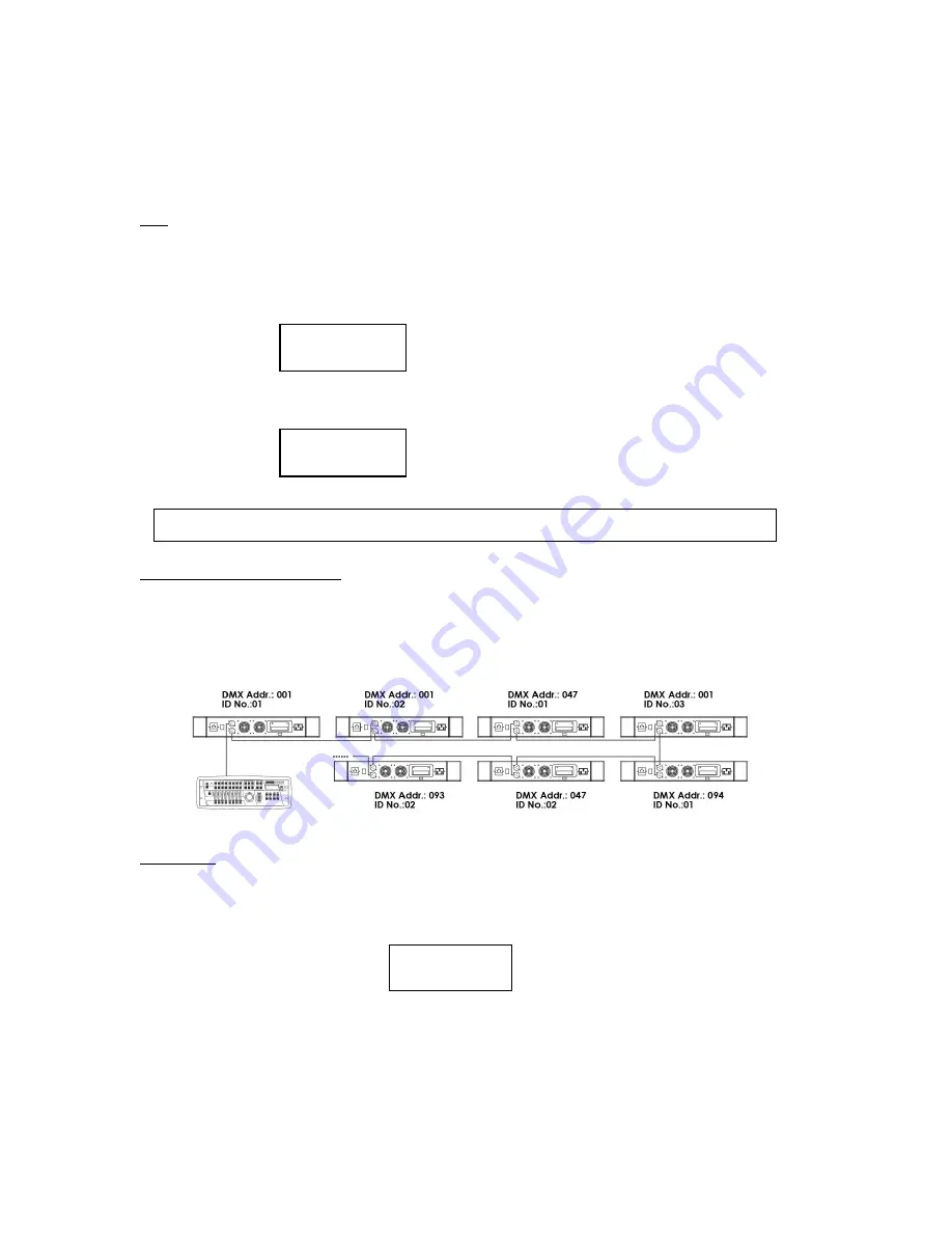
DMX CONTROL WITH ID NUMBER 

ID number is created for DMX fixture with large number of DMX channels and allows one to control multiple units 
independently or simultaneously on a small DMX console. The figure below shows a simple DMX layout. On the same 
starting channel, say 001, there are three units with 3 different ID numbers. You can use the 1st channel to target different 
units and backward channels to program. 


AUTO MODE 
 

In this mode, you can combine 12 editable, 6 built-in programs and running time of each program without external DMX 
controller. 
 
1. Press MENU button till System Mode [xxx] displayed, then use Up/Down button to select System Mode [Auto] and 
press Fun button to enter. LCD shows: 


2. Press Fun button to move forward and Up/Down button to select step (1-18) and Program number (1-18), time (1-240s) 
for each step/program. 
 
3. Press MENU button to exit and run in Auto mode. 


Addr  mode   ID 
[001]    1     1 

Addr  mode   ID 
[006]    3     1 

NOTE: ID number is activated only when Mode 5 is selected. Under Mode 1~4, ID number is invalid. 

Step   prog    time 
[1]      1      020 

Summary of Contents for LED Razor45

Page 1: ......

Page 2: ...ash is made of a new type of high temperature strength of engineering plastics and cast aluminum The fixture is designed and manufactured strictly following CE standards complying with international s...

Page 3: ...d on or near combustible substances Keep more than 50cm distance from wall for proper ventilation and air flow If your fixture is or has become damaged in any way it shall be exclusively replaced or r...

Page 4: ...f DMX channels and allows one to control multiple units independently or simultaneously on a small DMX console The figure below shows a simple DMX layout On the same starting channel say 001 there are...

Page 5: ...it in PROGRAM Auto and Sound mode to run the whole system In Master Slave operating mode all Slave units are to be set to Slave Mode and Slave ID is required for each Slave unit 1 Press MENU button go...

Page 6: ...press Fun button to enter Test Mode 2 Use Up Down button to select Test LED or Test Fan then press Fun button to go to Test LED or Test Fan 3 Press Up Down to test Red Green Blue White and Amber LEDs...

Page 7: ...onnectors Please refer to the diagram below DMX 512 Connection With DMX Terminator For installations where the DMX cable has to run a long distance or is in an electrically noisy environment it is rec...

Page 8: ...7 6 MENU NAVIGATION When navigating the menu Use UP button to move up Use DOWN button to move down Use FUN button to move right Use MENU button to move left...

Page 9: ...150 Colour 29 151 156 Colour 30 157 161 Colour 31 162 166 Colour 32 167 171 Colour 33 172 176 Colour 34 177 182 Colour 35 183 187 Colour 36 188 192 Colour 37 193 197 Colour 38 198 202 Colour 39 203 20...

Page 10: ...Brightness Adjust 0 100 6 Blue 000 255 Brightness Adjust 0 100 7 White 000 255 Brightness Adjust 0 100 8 Amber 000 255 Brightness Adjust 0 100 Section 2 9 Strobe 000 004 No Function 005 255 Strobe Sl...

Page 11: ...ds to Center 4 LED 1 Red 000 255 Brightness Adjust 0 100 5 LED 2 Green 000 255 Brightness Adjust 0 100 6 LED 3 Blue 000 255 Brightness Adjust 0 100 7 LED 4 White 000 255 Brightness Adjust 0 100 8 LED...

Page 12: ...000 255 Brightness Adjust 0 100 10 LED 6 Red 000 255 Brightness Adjust 0 100 11 LED 7 Green 000 255 Brightness Adjust 0 100 12 LED 8 Blue 000 255 Brightness Adjust 0 100 13 LED 9 White 000 255 Bright...

Page 13: ...ace lens kit and follow reverse steps to close the fixture IMPORTANT When replacing the lens assembly please make sure that the power is disconnected from the fixture beforehand LEDs on PCBs are sensi...

Page 14: ...13 10 UNIT OVERVIEW...

Page 15: ...accumulation of dust dirt etc 2 Clean the fan each week 3 A detailed electrical check by approved technician every three months is advised Ensure the circuit contacts are in good condition and preven...

Page 16: ......

Reviews: