background image


HiLink User manual EN 

 v 1.0.1 


  14 

3.8


S

YNCHRONIZATION 

O

UTPUT


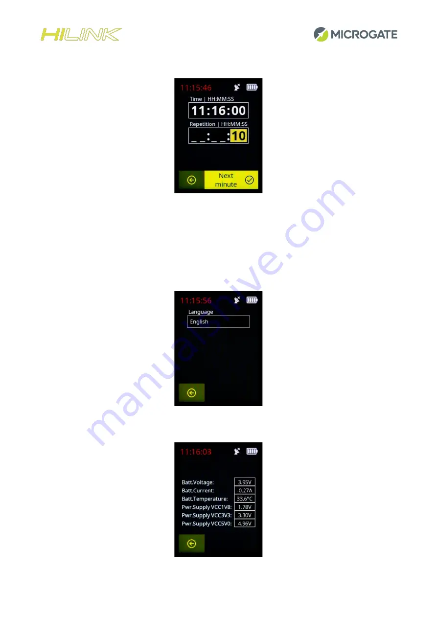
This menu is useful when we want to use HiLink as a synchronizer. By setting the time and the repetition time 
we will send a pulse on the green socket every repetition time starting from the indicated time. T

he “Next 

minute” button on the touch display allows you to pre

-load the time of the next full minute and then define 

only the repetition time. 

3.9


L

ANGUAGE


The HiLink menus can currently be displayed in Italian, English and German. 


3.10


S

YSTEM 

S

TATUS


Summary of Contents for Hilink

Page 1: ...User Manual Firmware Version 1 1 1 Manual Version 1 0 1 Issue Date 17 03 2022...

Page 2: ...3 1 Radio Transmission 11 3 3 2 Radio Frequency 11 3 3 3 Group ID 11 3 4 GPS and Time Zone 12 3 4 1 GPS Synchronization Mode 12 3 4 2 Time Zone 12 3 4 3 GPS Status 12 3 5 Test radio signal 12 3 6 Bri...

Page 3: ...in conjunction with EncRadio MF transmitters 25 6 4 RTPro and HiLink used in conjunction with EncRadio SF and Polifemo Radio SF transmitters 27 6 5 Racetime 2 and HiLink used as transmitter 28 6 6 Rac...

Page 4: ...ual EN v 1 0 1 4 1 HILINK GENERAL DESCRIPTION TNC connector for antenna USB C connector for power supply and PC connection Touch display Keyboard Status LED Line input Connector for cable connection t...

Page 5: ...5 DOWN Arrow button ENTER button for confirming menu and sending manual radio signal main menu Microgate ON OFF and Home button LINE 2 socket Earth socket GND LINE 1 socket Connector for stopwatch con...

Page 6: ...igured via software or remotely on one of the 68 available frequencies and can be supplied in the 10 mW power version as well as in the 500 mW version HiLink has a Bluetooth module for communication w...

Page 7: ...WARE Once the system is turned on using the Microgate ON OFF button the home screen gives us two options 1 Start a new session 2 Enter the settings menu 2 1 NEW SESSION The screen gives us the followi...

Page 8: ...ly selected settings GID Group ID represents a value that allows radio pulses to be received only from systems that have set the same Group ID Equivalent to the old radio channel concept of the old Li...

Page 9: ...alue and means that the radio protocol used in transmission is that of the HiLink new generation EncRadio if EncRadio mode is selected the transmission protocol is that of the old generation of LinkGa...

Page 10: ...e of pulse logic channel to be transmitted START STOP LAP1 LAP14 when a signal is received on the Green Line 1 and Red Line 2 sockets If the pulse is transmitted by pressing the Enter button bottom le...

Page 11: ...I have to closely follow multiple radio transmissions that could have the signals overlap 3 3 2 Radio Frequency This parameter represents the channel of the frequency used see Appendix Radio Frequenci...

Page 12: ...is valid the internal base synchronizes with the satellite time and then continues with an accuracy of 1 ppm Continuous in this mode once the satellite signal is valid the internal base continuously...

Page 13: ...er set to ON If the parameter is set to OFF the brightness is adjusted with the percentage indicated in the Set Brightness parameter 3 6 3 Set Brightness In the case of Auto Brightness Off it allows y...

Page 14: ...etition time we will send a pulse on the green socket every repetition time starting from the indicated time The Next minute button on the touch display allows you to pre load the time of the next ful...

Page 15: ...nt and temperature and other parameters related to the different supply voltages 3 11 TEST TIME BASE CALIBRATION This test checks the internal time base calibration when there is a valid GPS signal 3...

Page 16: ...ering a new number in the New Bib field using the touch display and the arrows and pressing the Confirm button on the display will assign the new bib number to the device 3 14 HISMART RSSI THRESHOLD T...

Page 17: ...HiLink User manual EN v 1 0 1 17 3 15 RESET DEFAULT This option returns the HiLink device to the factory default settings...

Page 18: ...is plugged in When charging is complete the LED will be a steady GREEN light If on the contrary you want to charge the device while it is on the external power supply symbol will appear at the top rig...

Page 19: ...obtain correct information By default a configuration HiSynch Enabled ON is active on ReiPro and RTPro which automatically synchronizes the time base of the stopwatch with that of HiLink when connecte...

Page 20: ...connection the first time after which you no longer need to do this HiLink must be connected to the RTPro stopwatch by following the steps below 1 From the RTPro main screen click on the settings ico...

Page 21: ...ual EN v 1 0 1 21 4 Verify that the Bluetooth and HiSynch functions on RTPRO are enabled 5 Select that device from the list of available devices and press connect 6 Wait until the device status is Con...

Page 22: ...lly compatible with previous generation Linkgate systems Encoder and Decoder First of all it is important to note that there are two ways to connect HiLink to RTPro By Cable using the specific cable C...

Page 23: ...o follow are as follows 6 1 1 The connection to the stopwatch by cable Connect HiLink to the RTPro stopwatch If you connect HiLink by cable no configuration needs to be done on the device 6 1 2 The co...

Page 24: ...es Line 1 LAP 1 or the next one Mode Mode Normal HiSmart Trigger 4 Very Far Settings Lines Line 1 STOP Mode Mode Normal HiSmart Trigger 4 Very Far You should also check that all the HiLink devices are...

Page 25: ...ribed in the previous parameter In the case of connection via BT the stopwatch must remain at a communication distance supported by BT technology approximately less than 50m 6 3 RTPRO AND HILINK USED...

Page 26: ...ON ON 434 0000 37 ON OFF ON ON 434 0500 39 OFF OFF ON ON 434 1000 41 ON ON OFF ON 434 1500 43 OFF ON OFF ON 434 2000 45 ON OFF OFF ON 434 2500 47 OFF OFF OFF ON 434 3000 49 ON ON ON OFF 434 3500 51 OF...

Page 27: ...without any need for specific configurations However the following parameters must be taken into account 1 The transmission frequency of the HiLink devices must be set to the following values Center...

Page 28: ...n always integrate it with new HiLink transmitters HiLink transmitters must be configured as follows Start Intermediate Finish Settings Lines Line 1 START Mode Mode EncRadio HiSmart Trigger 0 Disabled...

Page 29: ...Hz HIFamily FREQ Number LinkGate Radio multi frequency DIP SWITCH Switch 1 Switch 2 Switch 3 Switch 4 433 9000 33 ON ON ON ON 433 9500 35 OFF ON ON ON 434 0000 37 ON OFF ON ON 434 0500 39 OFF OFF ON O...

Page 30: ...HiLink device must be set to the following values In the case of SF transmission systems Center Frequency MHz HIFamily FREQ Number Linkgate Radio SF SF2 SF3 SF4 single frequency SF SF2 SF3 SF4 433 92...

Page 31: ...ON 434 3000 49 ON ON ON OFF 434 3500 51 OFF ON ON OFF 434 4000 53 ON OFF ON OFF 434 4500 55 OFF OFF ON OFF 434 5000 57 ON ON OFF OFF 434 5500 59 OFF ON OFF OFF 434 6000 61 ON OFF OFF OFF 434 6500 63...

Page 32: ...ink see HiSmart bib change menu or by the ProUpdater program that can be downloaded from the Microgate website The HiLink system allows you to configure the distance at which HiSmart will be detected...

Page 33: ...l HiSmart Trigger 4 Very Far Settings Lines Line 1 STOP Mode Mode Normal HiSmart Trigger 4 Very Far On the RTPro stopwatch for the Training Light program it is also possible to configure a parameter w...

Page 34: ...f the button is held down for less than 3 seconds the RED LED error signal is shown for 3 seconds and the device remains off This feature is designed to prevent the device from being turned on acciden...

Page 35: ...er the device is turned on the device is in Low Battery status 7 3 BATTERY LIFE With a full charge HiSmart will run for more than 14 hours Once low battery has been signalled the device still has 2 ho...

Page 36: ...e HILINK from the front The connection diagrams are provided for documentation purposes Microgate recommends using its original cables which are EC approved Female connector Binder 5 pole 240 8 1 CHRO...

Page 37: ...5750 20 433 6000 21 433 6250 22 433 6500 23 433 6750 24 433 7000 25 433 7250 26 433 7500 27 433 7750 28 433 8000 29 433 8250 30 433 8500 31 433 8750 32 433 9000 33 433 9250 34 433 9500 35 433 9750 36...

Page 38: ...N ON OFF ON 434 1500 43 OFF ON OFF ON 434 2000 45 ON OFF OFF ON 434 2500 47 OFF OFF OFF ON 434 3000 49 ON ON ON OFF 434 3500 51 OFF ON ON OFF 434 4000 53 ON OFF ON OFF 434 4500 55 OFF OFF ON OFF 434 5...

Reviews: