background image

Master Rhino Manual_

March 2020.docx


March 20 

Page 20 of 38 


10. 

SYSTEM MAINTENANCE 

  CRANKCASE OIL 

The RHINO pump unit is equipped with an hour meter and an automatic 

reminder to change pump oil; Red light, slow flash (does not affect 

operation).  See page 10 for instructions to reset light indicator. 


Initially the Crankcase Oil must be changed after the first 50 operating 

hours. 

After that it should be changed after every 500 hours of operation. 


Examples of 500 hours operation: 


15 weeks of 5 hour operation per day 


9 weeks of 8 hour operation per day 


6 weeks of 12 hour operation per day 


3 weeks of 24 hour operation per day 

Chart to the right indicates oil capacity for each pump 

SYNTHETIC 75w-90 GEAR OIL IS RECOMMENDED FOR ALL APPLICATIONS (Mobil One or Equal) 

In the event that 75w-90 is not available, synthetic 15w-50 Motor oil may be substituted (Mobil One or 

Equal) 


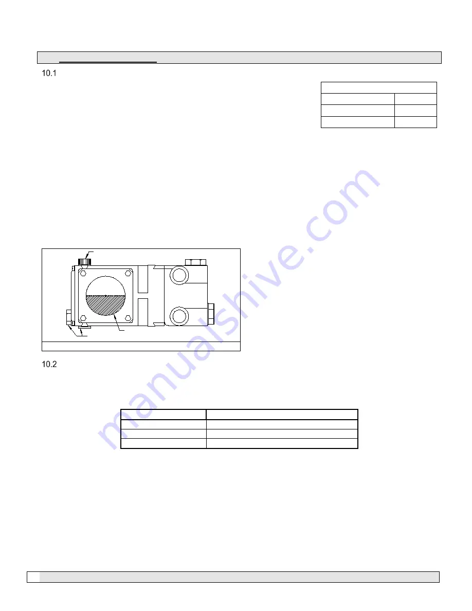
Figure 20 – Crankcase Oil Levels 


  ELECTRICAL MOTOR SERVICE 

Two types of electrical motors are used on the MicroCool

 pump modules.  Some small motors have sealed 

rotor bearings and some require lubrication periodically.  Refer to the motor nameplate for the type of motor. If 

the motor is equipped with external grease nipples refer to the chart below for lubrication instructions.    


Service Condition 

Time Intervals 

Standard 

Every 3 Years 

Severe 

Every 1 Year 

Seasonal 

Lubricate at beginning of season 


Electrical motors on the pump modules are pre-greased with a polyurea mineral oil NGLI grade 2-type grease 

unless stated otherwise on the motor nameplate.  Some compatible brands of polyurea mineral base type grease 

are: Chevron SRI #2, Rykon Premium #2, Shell Oil Doilum R or Texaco Polystar RB.  Motors are properly 

lubricated at the time of manufacture and do not need to be lubricated at the time of installation.   


NOTE: Over greasing bearings can cause premature bearing and/or motor failure.  The amount of grease added 

to the motor should be carefully controlled.  One crank of the grease gun handle is usually sufficient. 


Crankcase Oil Capacity 

Giant P420A 

30 fl oz. 

Giant  P470 

30 fl oz. 

Giant P536 

68 fl oz. 

FILL TO CENTER

OF SIGHT GLASS

OIL DRAIN

OIL FILL AND DIPSTICK


P400-P500 Giant Pump 

Summary of Contents for RHINO 15

Page 1: ...Master Rhino Manual_March 2020 docx March 20 Page 1 of 38 RHINO SERIES 2020 Installation Maintenance Manual Version 03 20 MicroCool 72216 Northshore t 103 104 Thousand Palms CA 92276 USA...

Page 2: ...RSE OSMOSIS WATER TREATMENT 6 3 INSTALLATION OF THE PUMP MODULE 7 3 1 POSITIONING THE PUMP MODULE 7 3 2 WATER SUPPLY AND CONNECTION 7 3 3 DRAINAGE FROM THE PUMP 7 4 PUMP MODULE POWER SUPPLY 7 4 1 CAUT...

Page 3: ...Y CONTROLS OPTIONAL UPGRADE 14 9 7 SETTING FOR HUMIDITY CONTROL ONLY 14 9 8 SETTING FOR TEMPERATURE CONTROL ONLY 14 9 9 SETTING FOR HUMIDITY CONTROL WITH TEMPERATURE OVERRIDE 14 9 10 SETTING FOR TEMPE...

Page 4: ...14 1 RHINO FRONT VIEW 27 14 2 RHINO BACK VIEW 28 14 3 RHINO RIGHT SIDE VIEW 29 14 4 RHINO LEFT SIDE VIEW 30 14 5 RHINO PLAN VIEW 31 14 6 RHINO FILTER AND BRACKET 32 14 7 CONTROL PANEL 1 33 14 8 CONTRO...

Page 5: ...MATION OIL CHANGE INTERVAL The crankcase oil must be changed after the first 50 hours of operation and from then on once every 500 hours SYNTHETIC 75W 90 GEAR OIL IS RECOMMENDED FOR ALL APPLICATIONS M...

Page 6: ...WATER TREATMENT Generally speaking most municipal water is suitable for atomization Well water river water and the like should be tested before atomizing If an analysis indicates any unusually high le...

Page 7: ...n All pump modules require a minimum of 20 P S I 1 40 BAR and a maximum of 90 P S I 6 20 BAR while in operation The pressure should always be constant and not fluctuate outside these ranges especially...

Page 8: ...e correct sized wiring be in conduit preferably liquid tight make the final connection to the high voltage terminal strip ELECTRICAL CONNECTIONS Wiring between the control panel and the pump unit is d...

Page 9: ...controller will increase or decrease the motor speed to maintain the required pressure 1 000 psi 69 Bar The controller is capable of increasing the speed frequency to a maximum of 50 Hz The rate of ch...

Page 10: ...s Use Teflon tape on all NPT threads and tighten each fitting firmly Do not apply tape to compression fittings or ball seat fittings Female swivel hose fitting 8 1 3 Press F1 to start the pump The RHI...

Page 11: ...a hard wired input switch into the electrical control panel on terminal 1 2 on TB1 yellow and blue terminal blocks Auto mode is also used if the internal 24 hour 7 day clocks and or internal temperat...

Page 12: ...ce 7 Display screen will indicate Stop Set Param Msg Config and Set with indicating selection 8 Use the buttons to move the selection indicator to Set Program and press OK 9 Use the buttons to move th...

Page 13: ...as CYCLE T the default setting is 1 minute on and 1 minute off but is disabled 2 To access enable and set cycle pulse times follow the steps in 9 2 Setting Auxiliary Parameters 3 To enable the cycle t...

Page 14: ...revert back to the operation screen after 30 seconds SETTING FOR HUMIDITY CONTROL ONLY 1 Set the temperature set point to 33 F 0 C off 33 F 1 C and on 34 F 1 C This forces the temp contact 2 Set the h...

Page 15: ...ires external contact F3 Stop Reset F4 Hold for 3 seconds to enter parameter settings Data Plate Press and hold F4 for 3 seconds The pump detail display will remain visible for 30 seconds Model number...

Page 16: ...mperature Temperature set point Current humidity Humidity set point Only active when temp and humid soft key is set to ON in parameter set only available with optional upgrade Auto Run Control Paramet...

Page 17: ...n auto time clock System pressure Hours of operation Pressure Relief Pump has stopped and is draining System pressure Drain Time Auto Cycle Run Pump is running on cycle time On timer System pressure H...

Page 18: ...the system locks out on a fault Frequency Inverter Fault Pump system has faulted on VFD fault 30 second restart delay is in process If VFD fault is cleared within 30 seconds pump will restart and oper...

Page 19: ...ing correctly and are in Auto Press F3 to reset if fault does not clear activate the prime and flush sequence by pressing F3 and F4 simultaneously This will flush the pump system with cool supply wate...

Page 20: ...icroCool pump modules Some small motors have sealed rotor bearings and some require lubrication periodically Refer to the motor nameplate for the type of motor If the motor is equipped with external g...

Page 21: ...abrasive surface SYSTEM FLUSH SHUT DOWN WINTERIZING If the system is to be SHUT DOWN for a period of time all automatic drain valves or end plugs should be removed and the complete system flushed Then...

Page 22: ...ation of the bulb and receptacle and gently plug the new bulb into the receptacle ensuring that it goes in all the way 4 Replace the receptacle onto the UV housing and reinstall the locking pin 5 The...

Page 23: ...module may be inadequate Check the following Inlet water pressure has dropped below 20 P S I 1 4 BAR correct water pressure Dirty filter elements inspect and replace if necessary Water supply turned o...

Page 24: ...uit or damaged Start with too short acceleration ramp Start with motor spinning without the Flying Start function F0072 Motor overload fault 60 s in 1 5xlnom P0156 P0157 P0158 setting is too low in re...

Page 25: ...time provided above shall constitute fulfillment of all liabilities of the seller to the purchaser with respect to or arising out of the goods whether based on contract negligence strict tort or othe...

Page 26: ...locations Page 1 of 1 Issued to MICROCOOL 72216 Northshore St Unit 103 104 THOUSAND PALMS CA 92276 This is to certify that representative samples o f INDUSTRIAL CONTROL PANELS USL CNL Industrial cont...

Page 27: ...Master Rhino Manual_March 2020 docx March 20 Page 27 of 38 14 RHINO ILLUSTRATIONS RHINO FRONT VIEW...

Page 28: ...Master Rhino Manual_March 2020 docx March 20 Page 28 of 38 RHINO BACK VIEW...

Page 29: ...Master Rhino Manual_March 2020 docx March 20 Page 29 of 38 RHINO RIGHT SIDE VIEW...

Page 30: ...Master Rhino Manual_March 2020 docx March 20 Page 30 of 38 RHINO LEFT SIDE VIEW...

Page 31: ...Master Rhino Manual_March 2020 docx March 20 Page 31 of 38 RHINO PLAN VIEW...

Page 32: ...Master Rhino Manual_March 2020 docx March 20 Page 32 of 38 RHINO FILTER AND BRACKET...

Page 33: ...Master Rhino Manual_March 2020 docx March 20 Page 33 of 38 CONTROL PANEL 1...

Page 34: ...Master Rhino Manual_March 2020 docx March 20 Page 34 of 38 CONTROL PANEL 2...

Page 35: ...Master Rhino Manual_March 2020 docx March 20 Page 35 of 38 CONTROL PANEL 3...

Page 36: ...Master Rhino Manual_March 2020 docx March 20 Page 36 of 38 CONTROL PANEL 4...

Page 37: ...Master Rhino Manual_March 2020 docx March 20 Page 37 of 38 RHINO SOLENOID...

Page 38: ...Master Rhino Manual_March 2020 docx March 20 Page 38 of 38 RHINO NOTES...

Reviews: