dsPIC30F6010
DS70119B-page 214
Advance Information
2004 Microchip Technology Inc.
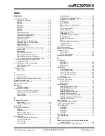
Data Access from Program Memory Using
Table Instructions................................................ 21
Data Access from, Address Generation...................... 20
Memory Map ............................................................... 19
Table Instructions
Program and EEPROM Characteristics ............................ 176
Program Counter................................................................. 12
Program Data Table Access ............................................... 22
Program Space Visibility
Window into Program Space Operation...................... 23
Programmable................................................................... 135
Programmable Digital Noise Filters..................................... 81
Programmer’s Model........................................................... 12
Diagram ...................................................................... 13
Programming Operations .................................................... 45
Algorithm for Program Flash ....................................... 45
Erasing a Row of Program Memory ............................ 45
Initiating the Programming Sequence ......................... 46
Loading Write Latches ................................................ 46
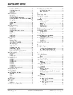
Protection Against Accidental Writes to OSCCON ........... 139
PWM Duty Cycle Comparison Units ................................... 89
Duty Cycle Register Buffers ........................................ 89
PWM Fault Pins .................................................................. 92
Priority ......................................................................... 92
PWM Operation During CPU Idle Mode.............................. 93
PWM Operation During CPU Sleep Mode .......................... 93
PWM Output and Polarity Control ....................................... 92
Output Pin Control ...................................................... 92
PWM Output Override......................................................... 91
PWM Period ........................................................................ 88
PWM Special Event Trigger ................................................ 93
Postscaler ................................................................... 93
PWM Time Base ................................................................. 87
Continuous Up/Down Counting Modes ....................... 87
Double Update Mode .................................................. 88
Free Running Mode .................................................... 87
Postscaler ................................................................... 88
Prescaler ..................................................................... 88
Single Shot Mode........................................................ 87
PWM Update Lockout ......................................................... 93
Q
QEA/QEB Input Characteristics ........................................ 189
QEI Module
External Clock Timing Requirements........................ 185
Index Pulse Timing Characteristics........................... 190
Index Pulse Timing Requirements ............................ 190
Operation During CPU Idle Mode ............................... 81
Operation During CPU Sleep Mode ............................ 81
Register Map............................................................... 83
Timer Operation During CPU Idle Mode ..................... 82
Timer Operation During CPU Sleep Mode.................. 81
Quadrature Decoder Timing Requirements ...................... 189
Quadrature Encoder Interface (QEI) Module ...................... 79
Quadrature Encoder Interface Interrupts ............................ 82
Quadrature Encoder Interface Logic................................... 80
R
Reset ........................................................................ 135, 140
Reset Sequence ................................................................. 39
Reset Sources ............................................................ 39
Reset Timing Characteristics............................................ 181
Reset Timing Requirements ............................................. 182
Resets
BOR, Programmable ................................................ 142
POR .......................................................................... 140
POR with Long Crystal Start-up Time....................... 142
POR, Operating without FSCM and PWRT .............. 142
S
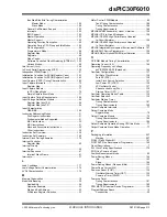
Simple Capture Event Mode
Capture Buffer Operation............................................ 71
Capture Prescaler....................................................... 71
Hall Sensor Mode ....................................................... 72
Input Capture in CPU Idle Mode................................. 72
Timer2 and Timer3 Selection Mode............................ 72
Simple OC/PWM Mode Timing Requirements ................. 187
Simple Output Compare Match Mode ................................ 76
Simple PWM Mode ............................................................. 76
Input Pin Fault Protection ........................................... 76
Period ......................................................................... 77
Single Pulse PWM Operation ............................................. 91
Software Simulator (MPLAB SIM) .................................... 158
Software Simulator (MPLAB SIM30) ................................ 158
Software Stack Pointer, Frame Pointer .............................. 12
CALL Stack Frame ..................................................... 27
SPI Mode
Slave Select Synchronization ..................................... 97
SPI1 Register Map...................................................... 98
SPI2 Register Map...................................................... 98
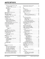
SPI Module ......................................................................... 95
Master Mode (CKE = 0).................................... 191
Master Mode (CKE = 1).................................... 192
Slave Mode (CKE = 1).............................. 193, 194
Timing Requirements
Master Mode (CKE = 0).................................... 191
Master Mode (CKE = 1).................................... 192
Slave Mode (CKE = 0)...................................... 193
Slave Mode (CKE = 1)...................................... 195
Word and Byte Communication .................................. 95
SPI Operation During CPU Idle Mode ................................ 97
SPI Operation During CPU Sleep Mode............................. 97
Status Register ................................................................... 12
Symbols Used in Opcode Descriptions ............................ 150
System Integration............................................................ 135
Overview................................................................... 135
Register Map ............................................................ 147
T
Temperature and Voltage Specifications
AC............................................................................. 177
DC ............................................................................ 164
Timer1 Module.................................................................... 57
Summary of Contents for dsPIC30F6010
Page 12: ...dsPIC30F6010 DS70119B page 10 Advance Information 2004 Microchip Technology Inc NOTES...
Page 32: ...dsPIC30F6010 DS70119B page 30 Advance Information 2004 Microchip Technology Inc NOTES...
Page 38: ...dsPIC30F6010 DS70119B page 36 Advance Information 2004 Microchip Technology Inc NOTES...
Page 50: ...dsPIC30F6010 DS70119B page 48 Advance Information 2004 Microchip Technology Inc NOTES...
Page 68: ...dsPIC30F6010 DS70119B page 66 Advance Information 2004 Microchip Technology Inc NOTES...
Page 72: ...dsPIC30F6010 DS70119B page 70 Advance Information 2004 Microchip Technology Inc NOTES...
Page 76: ...dsPIC30F6010 DS70119B page 74 Advance Information 2004 Microchip Technology Inc NOTES...
Page 86: ...dsPIC30F6010 DS70119B page 84 Advance Information 2004 Microchip Technology Inc NOTES...
Page 108: ...dsPIC30F6010 DS70119B page 106 Advance Information 2004 Microchip Technology Inc NOTES...
Page 116: ...dsPIC30F6010 DS70119B page 114 Advance Information 2004 Microchip Technology Inc NOTES...
Page 128: ...dsPIC30F6010 DS70119B page 126 Advance Information 2004 Microchip Technology Inc NOTES...
Page 150: ...dsPIC30F6010 DS70119B page 148 Advance Information 2004 Microchip Technology Inc NOTES...
Page 164: ...dsPIC30F6010 DS70119B page 162 Advance Information 2004 Microchip Technology Inc NOTES...
Page 208: ...dsPIC30F6010 DS70119B page 206 Advance Information 2004 Microchip Technology Inc NOTES...
Page 220: ...dsPIC30F6010 DS70119B page 220 Advance Information 2004 Microchip Technology Inc NOTES...
Page 221: ...2004 Microchip Technology Inc Advance Information DS70119B page 221 dsPIC30F6010 NOTES...


