


2004 Microchip Technology Inc.
Advance Information
DS70119B-page 61
dsPIC30F6010
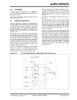
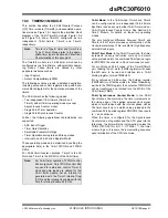
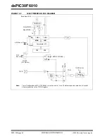
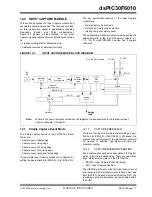
10.0 TIMER2/3 MODULE
This section describes the 32-bit General Purpose
(GP) Timer module (Timer2/3) and associated opera-
tional modes. Figure 10-1 depicts the simplified block
diagram of the 32-bit Timer2/3 module. Figure 10-2
and Figure 10-3 show Timer2/3 configured as two
independent 16-bit timers; Timer2 and Timer3,
respectively.
The Timer2/3 module is a 32-bit timer, which can be
configured as two 16-bit timers, with selectable operat-
ing modes. These timers are utilized by other
peripheral modules such as:
• Input Capture
• Output Compare/Simple PWM
The following sections provide a detailed description,
including setup and control registers, along with asso-
ciated block diagrams for the operational modes of the
timers.
The 32-bit timer has the following modes:
• Two independent 16-bit timers (Timer2 and
Timer3) with all 16-bit operating modes (except
Asynchronous Counter mode)
• Single 32-bit Timer operation
• Single 32-bit Synchronous Counter
Further, the following operational characteristics are
supported:
• ADC Event Trigger
• Timer Gate Operation
• Selectable Prescaler Settings
• Timer Operation during Idle and Sleep modes
• Interrupt on a 32-bit Period Register Match
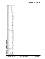
These operating modes are determined by setting the
appropriate bit(s) in the 16-bit T2CON and T3CON
SFRs.
For 32-bit timer/counter operation, Timer2 is the LS
Word and Timer3 is the MS Word of the 32-bit timer.
16-bit Mode:
In the 16-bit mode, Timer2 and Timer3
can be configured as two independent 16-bit timers.
Each timer can be set up in either 16-bit Timer mode or
16-bit Synchronous Counter mode. See Section 9.0,
Timer1 Module, for details on these two operating
modes.
The only functional difference between Timer2 and
Timer3 is that Timer2 provides synchronization of the
clock prescaler output. This is useful for high frequency
external clock inputs.
32-bit Timer Mode:
In the 32-bit Timer mode, the timer
increments on every instruction cycle up to a match
value, preloaded into the combined 32-bit period regis-
ter PR3/PR2, then resets to 0 and continues to count.
For synchronous 32-bit reads of the Timer2/Timer3
pair, reading the LS word (TMR2 register) will cause
the MS word to be read and latched into a 16-bit
holding register, termed TMR3HLD.
For synchronous 32-bit writes, the holding register
(TMR3HLD) must first be written to. When followed by
a write to the TMR2 register, the contents of TMR3HLD
will be transferred and latched into the MSB of the
32-bit timer (TMR3).
32-bit Synchronous Counter Mode:
In the 32-bit
Synchronous Counter mode, the timer increments on
the rising edge of the applied external clock signal,
which is synchronized with the internal phase clocks.
The timer counts up to a match value preloaded in the
combined 32-bit period register PR3/PR2, then resets
to ‘
0
’ and continues.
When the timer is configured for the Synchronous
Counter mode of operation and the CPU goes into the
Idle mode, the timer will stop incrementing, unless the
TSIDL (T2CON<13>) bit =
0
. If TSIDL =
1
, the timer
module logic will resume the incrementing sequence
upon termination of the CPU Idle mode.
Note:
Timer2 is a ‘Type B’ timer and Timer3 is a
‘Type C’ timer. Please refer to the appro-
priate timer type in Section 24.0 Electrical
Characteristics of this document.
Note:
For 32-bit timer operation, T3CON control
bits are ignored. Only T2CON control bits
are used for setup and control. Timer 2
clock and gate inputs are utilized for the
32-bit timer module, but an interrupt is
generated with the Timer3 interrupt flag
(T3IF) and the interrupt is enabled with the
Timer3 Interrupt Enable bit (T3IE).
Summary of Contents for dsPIC30F6010
Page 12: ...dsPIC30F6010 DS70119B page 10 Advance Information 2004 Microchip Technology Inc NOTES...
Page 32: ...dsPIC30F6010 DS70119B page 30 Advance Information 2004 Microchip Technology Inc NOTES...
Page 38: ...dsPIC30F6010 DS70119B page 36 Advance Information 2004 Microchip Technology Inc NOTES...
Page 50: ...dsPIC30F6010 DS70119B page 48 Advance Information 2004 Microchip Technology Inc NOTES...
Page 68: ...dsPIC30F6010 DS70119B page 66 Advance Information 2004 Microchip Technology Inc NOTES...
Page 72: ...dsPIC30F6010 DS70119B page 70 Advance Information 2004 Microchip Technology Inc NOTES...
Page 76: ...dsPIC30F6010 DS70119B page 74 Advance Information 2004 Microchip Technology Inc NOTES...
Page 86: ...dsPIC30F6010 DS70119B page 84 Advance Information 2004 Microchip Technology Inc NOTES...
Page 108: ...dsPIC30F6010 DS70119B page 106 Advance Information 2004 Microchip Technology Inc NOTES...
Page 116: ...dsPIC30F6010 DS70119B page 114 Advance Information 2004 Microchip Technology Inc NOTES...
Page 128: ...dsPIC30F6010 DS70119B page 126 Advance Information 2004 Microchip Technology Inc NOTES...
Page 150: ...dsPIC30F6010 DS70119B page 148 Advance Information 2004 Microchip Technology Inc NOTES...
Page 164: ...dsPIC30F6010 DS70119B page 162 Advance Information 2004 Microchip Technology Inc NOTES...
Page 208: ...dsPIC30F6010 DS70119B page 206 Advance Information 2004 Microchip Technology Inc NOTES...
Page 220: ...dsPIC30F6010 DS70119B page 220 Advance Information 2004 Microchip Technology Inc NOTES...
Page 221: ...2004 Microchip Technology Inc Advance Information DS70119B page 221 dsPIC30F6010 NOTES...


