2004 Microchip Technology Inc.
Advance Information
DS70119B-page 89
dsPIC30F6010
15.4
Center Aligned PWM
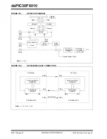
Center aligned PWM signals are produced by the mod-
ule when the PWM time base is configured in an Up/
Down Counting mode (see Figure 15-3).
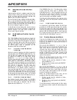
The PWM compare output is driven to the active state
when the value of the duty cycle register matches the
value of PTMR and the PWM time base is counting
downwards (PTDIR =
1
). The PWM compare output is
driven to the inactive state when the PWM time base is
counting upwards (PTDIR =
0
) and the value in the
PTMR register matches the duty cycle value.
If the value in a particular duty cycle register is zero,
then the output on the corresponding PWM pin will be
inactive for the entire PWM period. In addition, the out-
put on the PWM pin will be active for the entire PWM
period if the value in the duty cycle register is equal to
the value held in the PTPER register.
FIGURE 15-3:
CENTER ALIGNED PWM
15.5
PWM Duty Cycle Comparison
Units
There are four 16-bit special function registers (PDC1,
PDC2, PDC3 and PDC4) used to specify duty cycle
values for the PWM module.
The value in each duty cycle register determines the
amount of time that the PWM output is in the active
state. The duty cycle registers are 16-bits wide. The LS
bit of a duty cycle register determines whether the
PWM edge occurs in the beginning. Thus, the PWM
resolution is effectively doubled.
15.5.1
DUTY CYCLE REGISTER BUFFERS
The four PWM duty cycle registers are double buffered
to allow glitchless updates of the PWM outputs. For
each duty cycle, there is a duty cycle register that is
accessible by the user and a second duty cycle register
that holds the actual compare value used in the present
PWM period.
For edge aligned PWM output, a new duty cycle value
will be updated whenever a match with the PTPER reg-
ister occurs and PTMR is reset. The contents of the
duty cycle buffers are automatically loaded into the
duty cycle registers when the PWM time base is dis-
abled (PTEN =
0
) and the UDIS bit is cleared in
PWMCON2.
When the PWM time base is in the Up/Down Counting
mode, new duty cycle values are updated when the
value of the PTMR register is zero and the PWM time
base begins to count upwards. The contents of the duty
cycle buffers are automatically loaded into the duty
cycle registers when the PWM time base is disabled
(PTEN =
0
).
When the PWM time base is in the Up/Down Counting
mode with double updates, new duty cycle values are
updated when the value of the PTMR register is zero,
and when the value of the PTMR register matches the
value in the PTPER register. The contents of the duty
cycle buffers are automatically loaded into the duty
cycle registers when the PWM time base is disabled
(PTEN =
0
).
15.6
Complementary PWM Operation
In the Complementary mode of operation, each pair of
PWM outputs is obtained by a complementary PWM
signal. A dead-time may be optionally inserted during
device switching, when both outputs are inactive for a
short period (Refer to Section 15.7).
In Complementary mode, the duty cycle comparison
units are assigned to the PWM outputs as follows:
• PDC1 register controls PWM1H/PWM1L outputs
• PDC2 register controls PWM2H/PWM2L outputs
• PDC3 register controls PWM3H/PWM3L outputs
• PDC4 register controls PWM4H/PWM4L outputs
The Complementary mode is selected for each PWM
I/O pin pair by clearing the appropriate PMODx bit in the
PWMCON1 SFR. The PWM I/O pins are set to
Complementary mode by default upon a device Reset.
0
PTPER
PTMR
Value
Period
Period/2
Duty
Cycle
Summary of Contents for dsPIC30F6010
Page 12: ...dsPIC30F6010 DS70119B page 10 Advance Information 2004 Microchip Technology Inc NOTES...
Page 32: ...dsPIC30F6010 DS70119B page 30 Advance Information 2004 Microchip Technology Inc NOTES...
Page 38: ...dsPIC30F6010 DS70119B page 36 Advance Information 2004 Microchip Technology Inc NOTES...
Page 50: ...dsPIC30F6010 DS70119B page 48 Advance Information 2004 Microchip Technology Inc NOTES...
Page 68: ...dsPIC30F6010 DS70119B page 66 Advance Information 2004 Microchip Technology Inc NOTES...
Page 72: ...dsPIC30F6010 DS70119B page 70 Advance Information 2004 Microchip Technology Inc NOTES...
Page 76: ...dsPIC30F6010 DS70119B page 74 Advance Information 2004 Microchip Technology Inc NOTES...
Page 86: ...dsPIC30F6010 DS70119B page 84 Advance Information 2004 Microchip Technology Inc NOTES...
Page 108: ...dsPIC30F6010 DS70119B page 106 Advance Information 2004 Microchip Technology Inc NOTES...
Page 116: ...dsPIC30F6010 DS70119B page 114 Advance Information 2004 Microchip Technology Inc NOTES...
Page 128: ...dsPIC30F6010 DS70119B page 126 Advance Information 2004 Microchip Technology Inc NOTES...
Page 150: ...dsPIC30F6010 DS70119B page 148 Advance Information 2004 Microchip Technology Inc NOTES...
Page 164: ...dsPIC30F6010 DS70119B page 162 Advance Information 2004 Microchip Technology Inc NOTES...
Page 208: ...dsPIC30F6010 DS70119B page 206 Advance Information 2004 Microchip Technology Inc NOTES...
Page 220: ...dsPIC30F6010 DS70119B page 220 Advance Information 2004 Microchip Technology Inc NOTES...
Page 221: ...2004 Microchip Technology Inc Advance Information DS70119B page 221 dsPIC30F6010 NOTES...


