Microchip Technology BM62 User Manual Download Page 2

DS70005260C-page 2

 2016-2017 Microchip Technology Inc.

Information  contained  in  this  publication  regarding  device
applications and the like is provided only for your convenience
and may be superseded by updates. It is your responsibility to
ensure  that  your  application  meets  with  your  specifications.
MICROCHIP  MAKES  NO  REPRESENTATIONS  OR
WARRANTIES  OF  ANY  KIND  WHETHER  EXPRESS  OR
IMPLIED,  WRITTEN  OR  ORAL,  STATUTORY  OR
OTHERWISE, 

RELATED  TO  THE 

INFORMATION,

INCLUDING  BUT  NOT  LIMITED  TO  ITS  CONDITION,
QUALITY,  PERFORMANCE,  MERCHANTABILITY  OR
FITNESS  FOR  PURPOSE

Microchip  disclaims  all  liability

arising  from  this  information  and  its  use.  Use  of  Microchip
devices in life support and/or safety applications is entirely at
the buyer’s risk, and the buyer agrees to defend, indemnify and
hold  harmless  Microchip  from  any  and  all  damages,  claims,
suits,  or  expenses  resulting  from  such  use.  No  licenses  are
conveyed,  implicitly  or  otherwise,  under  any  Microchip
intellectual property rights unless otherwise stated.

Note the following details of the code protection feature on Microchip devices:

Microchip products meet the specification contained in their particular Microchip Data Sheet.

Microchip believes that its family of products is one of the most secure families of its kind on the market today, when used in the 
intended manner and under normal conditions.

There are dishonest and possibly illegal methods used to breach the code protection feature. All of these methods, to our 
knowledge, require using the Microchip products in a manner outside the operating specifications contained in Microchip’s Data 
Sheets. Most likely, the person doing so is engaged in theft of intellectual property.

Microchip is willing to work with the customer who is concerned about the integrity of their code.

Neither Microchip nor any other semiconductor manufacturer can guarantee the security of their code. Code protection does not 
mean that we are guaranteeing the product as “unbreakable.”

Code protection is constantly evolving. We at Microchip are committed to continuously improving the code protection features of our
products. Attempts to break Microchip’s code protection feature may be a violation of the Digital Millennium Copyright Act. If such acts
allow unauthorized access to your software or other copyrighted work, you may have a right to sue for relief under that Act.

Microchip received ISO/TS-16949:2009 certification for its worldwide 
headquarters, design and wafer fabrication facilities in Chandler and 
Tempe, Arizona; Gresham, Oregon and design centers in California 
and India. The Company’s quality system processes and procedures 
are for its PIC

®


MCUs and dsPIC

®

 DSCs, K

EE

L

OQ

®


code hopping 

devices, Serial EEPROMs, microperipherals, nonvolatile memory and 
analog products. In addition, Microchip’s quality system for the design 
and manufacture of development systems is ISO 9001:2000 certified.

QUALITY MANAGEMENT  SYSTEM 

CERTIFIED BY DNV 

== 

ISO/TS 16949


==


Trademarks

The Microchip name and logo, the Microchip logo, AnyRate, AVR, 
AVR logo, AVR Freaks, BeaconThings, BitCloud, CryptoMemory, 
CryptoRF, dsPIC, FlashFlex, flexPWR, Heldo, JukeBlox, K

EE

L

OQ

K

EE

L

OQ

 logo, Kleer, LANCheck, LINK MD, maXStylus, 

maXTouch, MediaLB, megaAVR, MOST, MOST logo, MPLAB, 
OptoLyzer, PIC, picoPower, PICSTART, PIC32 logo, Prochip 
Designer, QTouch, RightTouch, SAM-BA, SpyNIC, SST, SST 
Logo, SuperFlash, tinyAVR, UNI/O, and XMEGA are registered 
trademarks of Microchip Technology Incorporated in the U.S.A. 
and other countries.

ClockWorks, The Embedded Control Solutions Company, 
EtherSynch, Hyper Speed Control, HyperLight Load, IntelliMOS, 
mTouch, Precision Edge, and Quiet-Wire are registered 
trademarks of Microchip Technology Incorporated in the U.S.A.

Adjacent Key Suppression, AKS, Analog-for-the-Digital Age, Any 
Capacitor, AnyIn, AnyOut, BodyCom, chipKIT, chipKIT logo, 
CodeGuard, CryptoAuthentication, CryptoCompanion, 
CryptoController, dsPICDEM, dsPICDEM.net, Dynamic Average 
Matching, DAM, ECAN, EtherGREEN, In-Circuit Serial 
Programming, ICSP, Inter-Chip Connectivity, JitterBlocker, 
KleerNet, KleerNet logo, Mindi, MiWi, motorBench, MPASM, MPF, 
MPLAB Certified logo, MPLIB, MPLINK, MultiTRAK, NetDetach, 
Omniscient Code Generation, PICDEM, PICDEM.net, PICkit, 
PICtail, PureSilicon, QMatrix, RightTouch logo, REAL ICE, Ripple 
Blocker, SAM-ICE, Serial Quad I/O, SMART-I.S., SQI, 
SuperSwitcher, SuperSwitcher II, Total Endurance, TSHARC, 
USBCheck, VariSense, ViewSpan, WiperLock, Wireless DNA, and 
ZENA are trademarks of Microchip Technology Incorporated in the 
U.S.A. and other countries.

SQTP is a service mark of Microchip Technology Incorporated in 
the U.S.A.

Silicon Storage Technology is a registered trademark of Microchip 
Technology Inc. in other countries.

GestIC is a registered trademark of Microchip Technology 
Germany II GmbH & Co. KG, a subsidiary of Microchip Technology 
Inc., in other countries. 

All other trademarks mentioned herein are property of their 
respective companies.

© 2016-2017, Microchip Technology Incorporated, All Rights 
Reserved. 

ISBN: 

978-1-5224-2332-4

Summary of Contents for BM62

Page 1: ...2016 2017 Microchip Technology Inc DS70005260C BM62 Evaluation Board EVB User s Guide...

Page 2: ...ceived ISO TS 16949 2009 certification for its worldwide headquarters design and wafer fabrication facilities in Chandler and Tempe Arizona Gresham Oregon and design centers in California and India Th...

Page 3: ...hapter 3 Getting Started 3 1 Requirements 23 3 2 Getting Started with the BM62 EVB 24 3 3 Application Demonstration 24 3 4 Configuring BM62 Stereo Audio Module 26 3 5 Updating EEPROM Parameters 43 3 6...

Page 4: ...BM62 EVB User s Guide DS70005260C Page 4 2016 2017 Microchip Technology Inc NOTES...

Page 5: ...about how to establish the Bluetooth connection using the BM62 EVB Appendix A Emulating Host MCU provides information about how to emulate Host MCU using SPK Command Set Tool Appendix B Schematics pro...

Page 6: ...Sample source code define START Filenames autoexec bat File paths c mcc18 h Keywords _asm _endasm static Command line options Opa Opa Bit values 0 1 Constants 0xFF A Italic Courier New A variable arg...

Page 7: ...ort via our web site at http www microchip com This web site makes files and information easily available to customers Accessible by most Internet browsers the web site contains the following informat...

Page 8: ...n on the Microchip in circuit emulator MPLAB REAL ICE In Circuit Debuggers The latest information on the Microchip in circuit debugger MPLAB ICD 3 MPLAB X IDE The latest information on Microchip MPLAB...

Page 9: ...pdates Updated 3 2 Getting Started with the BM62 EVB Updated 3 4 Configuring BM62 Stereo Audio Module Updated 3 7 BLE Demonstration Added 3 8 NFC Demonstration Minor updates to text and formatting wer...

Page 10: ...BM62 EVB User s Guide DS70005260C Page 10 2016 2017 Microchip Technology Inc NOTES...

Page 11: ...interface for plug and play capability and also has status LEDs which enable rapid prototyping and faster time to market Along with the BM62 EVB software tools and applications are provided to demonst...

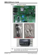
Page 12: ...icrochip Technology Inc FIGURE 1 1 BM62 EVB KIT CONTENTS Note If you are missing any part of the BM62 EVB kit contact a Microchip sales office for assistance A list of Microchip offices for sales and...

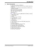
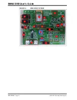
Page 13: ...RoHS compliant Figure 1 2 illustrates the top view of the BM62 EVB with the following components 1 BM62SPKS1MC2 module 2 Three status LEDs 3 NFC tag 4 Li Ion battery connector JP19 JP20 5 USB connect...

Page 14: ...BM62 EVB User s Guide DS70005260C Page 14 2016 2017 Microchip Technology Inc FIGURE 1 2 BM62 EVB TOP VIEW...

Page 15: ...RDWARE FEATURES The following list provides the details of each component in the BM62 EVB For detailed information about the location of these components refer to Figure 1 2 2 1 1 Power Supply Users c...

Page 16: ...ckward SW5 Skip the audio track forward SW9 Increase volume SW10 Decrease volume SW11 Reset button SW12 Mode switch SW46 Button for 3W Class D stereo amplifier signal connection SW48 and SW49 Buttons...

Page 17: ...de Switch SW46 Switch 46 PIN Definition On board 3W Class D stereo amplifier signal connection default on board stereo ampli fier 1 ON Amplifier power 2 ON L CH signal 3 ON R CH signal 4 ON Amplifier...

Page 18: ...User defined UI configuration dependent 2 1 5 Jumpers and Headers The following are jumpers and headers J1 J6 JP19 JP20 JP22 JP23 JP26 available on the BM62 EVB Figure 2 2 illustrates the GPIO header...

Page 19: ...he interface to connect an external MCU to the BM62 EVB over UART Figure 2 3 illustrates the external MCU header J6 and Table 2 5 provides the pin details and descriptions TABLE 2 4 GPIO HEADER J1 Par...

Page 20: ...nd descriptions FIGURE 2 4 BATTERY CONNECTOR JP20 AND JP19 TABLE 2 5 EXTERNAL MCU HEADER J6 Part Number Pin Description JP2 1 NC 2 HCI_RXD 3 NC 4 HCI_TXD 5 GND 6 GND 7 NC 8 RST_N 9 NC 10 MFB for RX_IN...

Page 21: ...e JP22 pin details and descriptions FIGURE 2 5 MIC JP22 Figure 2 6 illustrates the audio output header JP23 and Table 2 8 provides the pin details and descriptions FIGURE 2 6 AUDIO OUTPUT HEADER JP23...

Page 22: ...c Figure 2 7 illustrates the external amplifier header JP26 and Table 2 9 provides the pin details and descriptions FIGURE 2 7 EXTERNAL AMPLIFIER HEADER JP26 TABLE 2 9 EXTERNAL AMPLIFIER HEADER JP26 P...

Page 23: ...emonstration 3 1 REQUIREMENTS The following hardware and software components are required for getting started with the BM62 EVB 3 1 1 Hardware Requirements BM62 EVB Bluetooth enabled smartphone Androi...

Page 24: ...with the host device 7 Once the connection is established LED1 blue will blink twice at regular inter vals It will display as connected in the Bluetooth settings of the smartphone With the default se...

Page 25: ...ming voice call from a paired smartphone Per form the following actions for demonstration Refer to Figure 3 2 1 Establish a connection between the BM62 EVB and a host device using the procedure listed...

Page 26: ...see the effect of the customized parameters 3 4 1 UI Tool Configuration The User Interface UI tool is a configuration tool which enables the user to change the parameters of the BM62 stereo audio modu...

Page 27: ...default UI parameter text file provided with the UI tool for the BM62 stereo audio module and then click Open Figure 3 5 FIGURE 3 5 LOADING DEFAULT UI PARAMETERS 4 After selecting the UI parameters se...

Page 28: ...upported Profile and audio line in function Button and set the following parameters as illustrated in Figure 3 7 a Select the UART Command check box which allows the module to be con trolled by the MC...

Page 29: ...Settings dialog with various options tabs is dis played for parameter configuration In the Sys Setup2 tab in the Indication 1 Setting section enable External Amplifier Indication as illustrated in Fig...

Page 30: ...ogy Inc 7 After setting up the parameters click Finish A notification displays to check the EEPROM size on the system Click OK Figure 3 9 FIGURE 3 9 EEPROM NOTIFICATION 8 Click Save to save these UI p...

Page 31: ...ed 2016 2017 Microchip Technology Inc DS70005260C Page 31 9 From the Save As window select the file location and then click Save Figure 3 11 FIGURE 3 11 SAVE AS WINDOW 10 After saving the UI parameter...

Page 32: ...audio signal processing functions To configure the DSP parameters perform the following actions 1 Open the DSP tool A dialog displays various options tabs to configure the parameters as illustrated in...

Page 33: ...Getting Started 2016 2017 Microchip Technology Inc DS70005260C Page 33 2 From the Voice Function tab set the parameters as illustrated in Figure 3 13 FIGURE 3 13 DSP VOICE FUNCTION SETTING...

Page 34: ...BM62 EVB User s Guide DS70005260C Page 34 2016 2017 Microchip Technology Inc 3 From the Audio Function tab set the parameters as illustrated in Figure 3 14 FIGURE 3 14 DSP AUDIO FUNCTION SETTING...

Page 35: ...Getting Started 2016 2017 Microchip Technology Inc DS70005260C Page 35 4 Click Save to save these DSP parameters as txt file Figure 3 15 FIGURE 3 15 SAVING DSP PARAMETERS...

Page 36: ...Guide DS70005260C Page 36 2016 2017 Microchip Technology Inc 5 After saving the DSP parameters from the notification pop up click OK Figure 3 16 Click Exit to exit the DSP tool settings FIGURE 3 16 SA...

Page 37: ...Next to continue with the configuration settings Figure 3 17 FIGURE 3 17 MPET TOOL SETTING 2 Select UI Patch Only to merge the UI and the DSP parameters and then click Next as illustrated in Figure 3...

Page 38: ...age 38 2016 2017 Microchip Technology Inc FIGURE 3 18 MERGE UI AND DSP PARAMETERS 3 Click Browse to load the default bin file provided with the MPET tool From the Open window select the default bin fi...

Page 39: ...tting Started 2016 2017 Microchip Technology Inc DS70005260C Page 39 FIGURE 3 19 LOADING DEFAULT BIN FILE 4 The bin file description displays Click Next Figure 3 20 FIGURE 3 20 DEFAULT BIN FILE SETTIN...

Page 40: ...n to load the UI and the DSP parameters txt file into the MPET tool to merge with the EEPROM table and then click Next as illustrated in Figure 3 21 FIGURE 3 21 CUSTOMIZED SETTINGS TO MERGE 6 Select a...

Page 41: ...arted 2016 2017 Microchip Technology Inc DS70005260C Page 41 FIGURE 3 22 SELECTING OUTPUT FILE NAME AND PATH 7 Click Generate to generate the EEPROM table ipf file Figure 3 23 FIGURE 3 23 GENERATE EEP...

Page 42: ...patch file can be selected or ignored Click Next Figure 3 24 FIGURE 3 24 CALIBRATION PARAMETER CHECK 9 After generating the merged EEPROM table ipf file click Finish to exit the wizard Figure 3 25 Not...

Page 43: ...ROM PARAMETERS Perform the following actions to update the EEPROM parameters 1 Set switch SW12 to Test Mode Figure 3 26 FIGURE 3 26 SWITCH SW12 IN TEST MODE 2 Connect the BM62 EVB to a PC using a micr...

Page 44: ...7 EEPROM PARAMETER SETUP 3 Open the EEPROM tool and the tool window will display see Figure 3 28 FIGURE 3 28 EEPROM TOOL Note Download and install the EEPROM tool which is available on the Microchip w...

Page 45: ...as illustrated in Figure 3 29 FIGURE 3 29 EEPROM TOOL SETTINGS 5 Click Browse and load the generated patch file ipf to write the EEPROM parameter table on the BM62 EVB Figure 3 30 Note The patch file...

Page 46: ...2016 2017 Microchip Technology Inc FIGURE 3 30 LOADING GENERATED PATCH FILE 6 Click Write to program the EEPROM parameters on the BM62 EVB After pro gramming the EEPROM parameters a message is display...

Page 47: ...17 Microchip Technology Inc DS70005260C Page 47 FIGURE 3 31 WRITE EEPROM 7 Click Exit and remove the micro USB cable Next set SW12 to Application mode Figure 3 32 and reboot FIGURE 3 32 SWITCH SW12 IN...

Page 48: ...the BM62 EVB to a PC using a micro USB cable as illustrated in Figure 3 34 The default LED behavior in Write Flash mode is that LED1 and LED2 blue and red will blink LED3 green is on and this is an I...

Page 49: ...rowse to select the flash code files hex files downloaded from the Microchip web site Figure 3 36 FIGURE 3 36 LOADING FLASH CODE FILES 5 Click Update to write the flash code on the BM62 EVB Figure 3 3...

Page 50: ...een the BM62 EVB and a smartphone Perform the following steps for demonstration 1 Set switch SW12 to Application mode see Figure 3 32 2 Connect the BM62 EVB to a PC using micro USB cable as illustrate...

Page 51: ...BM62 EVB to a smartphone that supports the BLE Bluetooth pro files 5 Download and install the mBIoT Utility app available at the Apple Store for iPhone or at the Google Play Store for Android For this...

Page 52: ...ip Technology Inc FIGURE 3 40 SELECT BM78 BM6X BLE UART 7 The smartphone will display a list of discoverable BLE devices Click LE_Dual_SPK to connect Under the Connected Device tab click LE_Dual_SPK c...

Page 53: ...Page 53 8 Click Transparent and then select Display Data to enter message for transmission see Figure 3 42 FIGURE 3 42 TRANSPARENT PAGE Note Download and install the SPKCommandSetTool exe file which...

Page 54: ...ology Inc 9 Open the SPKCommandSetTool exe program on a PC to emulate the MCU and a window is displayed Figure 3 43 10 Specify the COM Port and then click Open 11 Click the SPP tab 12 Select BT Chat c...

Page 55: ...nology Inc DS70005260C Page 55 13 Figure 3 44 illustrates the data transmission between the mBIoT app and the SPKCommandSetTool FIGURE 3 44 DATA TRANSMISSION Note It is not necessary to use same devic...

Page 56: ...logy Inc 3 8 NFC DEMONSTRATION In BM62 EVB the NFC trigger circuit is connected to the BM62 module A smartphone with built in NFC is used to trigger the NFC function of the BM62 EVB Figure 3 45 illus...

Page 57: ...following parameters as illustrated in Figure 3 46 a Select the NFC Detect check box which allows the module to enable the NFC antenna on the BM62 EVB b Select the NFC check box to assign the GPIO pi...

Page 58: ...BM62 EVB User s Guide DS70005260C Page 58 2016 2017 Microchip Technology Inc NOTES...

Page 59: ...ndependent of the Host MCU However the user can use the UART interface and SPK Command Set Tool to emulate Host MCU connected over UART Enable UART Command in the Main Feature dia log as illustrated i...

Page 60: ...70005260C Page 60 2016 2017 Microchip Technology Inc FIGURE A 2 SPK COMMAND SET TOOL SETTINGS 4 Once COM Port is enabled select System tab and then click Power On as illus trated in Figure A 3 FIGURE...

Page 61: ...Emulating Host MCU 2016 2017 Microchip Technology Inc DS70005260C Page 61 5 Next click Enter Pairing Mode to enable pairing see Figure A 4 FIGURE A 4 ENABLE PAIRING MODE...

Page 62: ...BM62 EVB User s Guide DS70005260C Page 62 2016 2017 Microchip Technology Inc NOTES...

Page 63: ...BM62 EVB USER S GUIDE 2016 2017 Microchip Technology Inc DS70005260C Page 63 Appendix B Schematics B 1 REFERENCE SCHEMATICS FIGURE B 1 BM62 EVB SCHEMATICS...

Page 64: ...BM62 EVB User s Guide DS70005260C Page 64 2016 2017 Microchip Technology Inc FIGURE B 2 INPUT OUTPUT TEST FIGURE B 3 STATUS LEDS...

Page 65: ...Schematics 2016 2017 Microchip Technology Inc DS70005260C Page 65 FIGURE B 4 NFC TAG CIRCUIT...

Page 66: ...BM62 EVB User s Guide DS70005260C Page 66 2016 2017 Microchip Technology Inc FIGURE B 5 POWER SUPPLY FIGURE B 6 EXTERNAL MCU INTERFACE...

Page 67: ...Schematics 2016 2017 Microchip Technology Inc DS70005260C Page 67 FIGURE B 7 USB TO UART INTERFACE...

Page 68: ...BM62 EVB User s Guide DS70005260C Page 68 2016 2017 Microchip Technology Inc FIGURE B 8 UART INTERFACE...

Page 69: ...Schematics 2016 2017 Microchip Technology Inc DS70005260C Page 69 FIGURE B 9 SWITCH SW12 CONFIGURATION FIGURE B 10 POWER SOURCE...

Page 70: ...BM62 EVB User s Guide DS70005260C Page 70 2016 2017 Microchip Technology Inc FIGURE B 11 AUDIO TEST INTERFACE...

Page 71: ...Schematics 2016 2017 Microchip Technology Inc DS70005260C Page 71 FIGURE B 12 EXTERNAL AMPLIFIER SWITCH AND CONNECTOR...

Page 72: ...BM62 EVB User s Guide DS70005260C Page 72 2016 2017 Microchip Technology Inc FIGURE B 13 SPEAKER FIGURE B 14 MICROPHONE...

Page 73: ...Schematics 2016 2017 Microchip Technology Inc DS70005260C Page 73 FIGURE B 15 AUXILIARY INPUT FIGURE B 16 MFB AND RESET PUSH BUTTON...

Page 74: ...BM62 EVB User s Guide DS70005260C Page 74 2016 2017 Microchip Technology Inc FIGURE B 17 MUSIC CONTROL PUSH BUTTONS FIGURE B 18 SLIDE SWITCH...

Page 75: ...2016 2017 Microchip Technology Inc DS70005260C Page 75 NOTES...

Page 76: ...0 China Xian Tel 86 29 8833 7252 China Xiamen Tel 86 592 2388138 China Zhuhai Tel 86 756 3210040 ASIA PACIFIC India Bangalore Tel 91 80 3090 4444 India New Delhi Tel 91 11 4160 8631 India Pune Tel 91...

Reviews: