

Calibration Procedure
2015 Microchip Technology Inc.
DS50002379A-page 23
3.3
CURRENT CALIBRATION WITH INDUCTOR TEMPERATURE
MEASUREMENT
1.
Select Developer from the PMBMonitor GUI main menu, then choose the
Calibration
tab.
2.
Choose a low test current (except zero, for example, 1A) and write the value in
the first “Current” field in the IOUT Settings Panel. Set this current on the external
load as accurate as possible. Press the corresponding
Read
button. A value will
appear in the corresponding “Voltage” field.
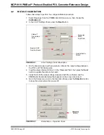
FIGURE 3-4:
IOUT Settings Panel.
3.
Choose a high test current (at best, the highest load current, for example, 17A),
write the value in the second “Current” field and set this output current on the
external load. Press the corresponding
Read
button. Write down the value that
appears in the second “Voltage” field.
4.
Press the
Calculate
button. The values in the “ADC(T0)”, “Coefficient-X1” and
“Coefficient-X0” fields may update once the calculations are done.
5.
Press
Send
from the bottom of the IOUT Settings Panel.
Input the Low
Test Current
Input the High
Test Current
Updateable Values
after Pressing
Calculate Button
Updates the Value
of the Temperature
Coefficient
Updates the
Current Calibration
WARNING
Keep constant board temperature around ambient during Steps 2 to 5; therefore, all
these measurements should be done as fast as possible and/or provide adequate
cooling.