

MCP19111 PMBus™ Protocol-Enabled POL Converter Reference Design
DS50002379A-page 18
2015 Microchip Technology Inc.
2.2
GETTING STARTED
The MCP19111 PMBus™ Protocol-Enabled Point-of-Load Converter Reference
Design is fully assembled and tested to evaluate and demonstrate the MCP19111
capabilities.
2.2.1
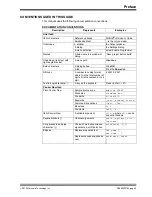
Necessary Instruments and Tools
• Adjustable DC Power Supply with 0V-15V/5 ADC
Range Output Capability
• Electronic Load with at least 25A Current Capability and Load Stepping Capability
• Digital Oscilloscope with a Minimum Bandwidth of 50 MHz
• Digital Voltmeter/Ammeter
• Optionally, a Network Analyzer/Bode Plot Analyzer for Control Loop Analyzing
• PC with PMBMonitor GUI Pre-Installed
• USB-A to mini-USB Cable
• Wires for Connections, Capable to Sustain High Currents:
- 5A for the connection between the adjustable DC power supply and board
- 20A for the connection between the board and the electronic load
2.2.2
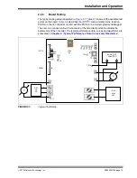
Setup Procedure
To power-up the MCP19111 PMBus™ Protocol-Enabled Point-of-Load Converter
Reference Design, the following steps must be completed:
1.
Connect the electronic load to the J2 connector of the demo board; the Positive
(+) and Negative (–) connector pins are marked on the board silkscreen.
2.
Connect the adjustable DC power supply to the J1 connector of the demo board;
the Positive (+) and Negative (–) connector pins are marked on the board
silkscreen.
3.
Supply 12V from the adjustable power source.
4.
Connect the test board to a PC with the PMBMonitor GUI pre-installed via a
USB-A to mini-USB cable (J3 connector).
5.
After powering up, press the push button, BT1, to turn on the output voltage.
Alternatively, the output may be turned on from the PMBMonitor GUI
ON
button
(under
Status>Operation Panel
).
6.
The board is factory set to deliver 1.2V at 20A maximum, with the loop adjusted
for optimum performance and current measurement performed via the auxiliary
op amp. If different settings are desired, changes may be performed in
several ways:
- Via the PMBus to USB on-board interface – refer to the
“PMBus™
Monitoring Graphical User Interface User’s Guide”
(DS50002380)
for details.
- Via PMBus – the user must connect a PMBus master via the I
2
C interface
of the board, connector J1.
- By user-developed software that may be loaded into the MCP19111
J2 connector using PICkit™ 3 or another suitable programming tool.