Microchip Technology ARD00609 User Manual Download Page 10

Preface

 2015 Microchip Technology Inc.

DS50002379A-page 9

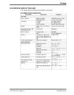
CONVENTIONS USED IN THIS GUIDE

This manual uses the following documentation conventions:

DOCUMENTATION CONVENTIONS

Description

Represents

Examples

Arial font:

Italic characters

Referenced books

MPLAB

®

 IDE User’s Guide

Emphasized text

...is the 

only

 compiler...

Initial caps

A window

the Output window

A dialog

the Settings dialog

A menu selection

select Enable Programmer

Quotes

A field name in a window or 
dialog

“Save project before build”

Underlined, italic text with 
right angle bracket

A menu path

File>Save

Bold characters

A dialog button

Click

 OK

A tab

Click the 

Power

 tab

N‘Rnnnn

A number in verilog format, 
where N is the total number of 
digits, R is the radix and n is a 
digit.

4‘b0010, 2‘hF1

Text in angle brackets < >

A key on the keyboard

Press <Enter>, <F1>

Courier New font:

Plain Courier New

Sample source code

#define START

Filenames

autoexec.bat

File paths

c:\mcc18\h

Keywords

_asm, _endasm, static

Command-line options

-Opa+, -Opa-

Bit values

0, 1

Constants

0xFF, ‘A’

Italic Courier New

A variable argument

file

.o

, where 

file

 can be 

any valid filename

Square brackets [ ]

Optional arguments

mcc18 [options] 

file


[options]

Curly brackets and pipe 
character: { | }

Choice of mutually exclusive 
arguments; an OR selection

errorlevel {0|1}

Ellipses...

Replaces repeated text

var_name [, 
var_name...]

Represents code supplied by 
user

void main (void)
{ ...
}

Summary of Contents for ARD00609

Page 1: ...ss mainly focus on the distribution of electronic components Line cards we deal with include Microchip ALPS ROHM Xilinx Pulse ON Everlight and Freescale Main products comprise IC Modules Potentiometer...

Page 2: ...2015 Microchip Technology Inc DS50002379A MCP19111 PMBus Protocol Enabled Point of Load POL Converter Reference Design User s Guide...

Page 3: ...tempts to break Microchip s code protection feature may be a violation of the Digital Millennium Copyright Act If such acts allow unauthorized access to your software or other copyrighted work you may...

Page 4: ...2015 Microchip Technology Inc DS50002379A page 3 Object of Declaration MCP19111 PMBus Protocol Enabled POL Converter Reference Design...

Page 5: ...MCP19111 PMBus Protocol Enabled POL Converter Reference Design DS50002379A page 4 2015 Microchip Technology Inc NOTES...

Page 6: ...troduction 13 1 2 MCP19111 Device Short Overview 13 1 3 What is the MCP19111 PMBus Protocol Enabled Point of Load Converter Reference Design 15 1 4 System Requirements 15 1 4 1 The Development System...

Page 7: ...Board Schematic 1 34 A 3 Board Schematic 2 35 A 4 Board Top Layer 36 A 5 Board Top Copper 36 A 6 Board Mid Layer 1 37 A 7 Board Mid Layer 2 37 A 8 Board Bottom Layer 38 A 9 Board Bottom Copper 38 App...

Page 8: ...stomer needs so some actual dialogs and or tool descriptions may differ from those in this document Please refer to our web site www microchip com to obtain the latest documentation available Document...

Page 9: ...P19111 PMBus Protocol Enabled Point of Load Converter Reference Design Chapter 3 Calibration Procedure Includes instructions on the calibration procedure of the MCP19111 PMBus Protocol Enabled Point o...

Page 10: ...dialog button Click OK A tab Click the Power tab N Rnnnn A number in verilog format where N is the total number of digits R is the radix and n is a digit 4 b0010 2 hF1 Text in angle brackets A key on...

Page 11: ...ser s Guide DS50002380 This user s guide describes how to use the PMBus Monitoring Graphical User Interface GUI TB3139 MCP19111 PMBus Firmware Technical Brief DS90003139 This technical brief describes...

Page 12: ...itor and MPLAB SIM Simulator as well as general editing and debugging features Programmers The latest information on Microchip programmers These include production programmers such as MPLAB REAL ICE I...

Page 13: ...HER SIMILAR COSTS MICROCHIP DISCLAIMS ALL LIABILITY ARISING FROM THIS INFORMATION AND ITS USE USE OF MICROCHIP DEVICES IN LIFE SUPPORT AND OR SAFETY APPLICATIONS IS ENTIRELY AT THE BUYER S RISK AND TH...

Page 14: ...efficiently operate from a single 4 5V to 32V supply It features integrated synchronous drivers a bootstrap device internal linear regulator and 4000 words of nonvolatile memory all in a space saving...

Page 15: ...logy Inc FIGURE 1 1 MCP19111 Typical Application HDRV BOOT PHASE LDRV VIN VDD VDR ISEN ISEN VSEN VSEN GND PGND GPB0 GPA7 GPA4 GPA1 GPB6 GPB7 GPA3 GPB2 GPA2 GPA5 GPB4 GPB5 GPA0 GPB1 GPA6 MCLR ICDCLK IC...

Page 16: ...eveloped firmware see Section 1 4 1 The Development System s Components tailoring it to the application The evaluation board contains headers for In Circuit Serial Programming ICSP as well as I2 C and...

Page 17: ...ove is coded in C and thus requires a C compiler C compilers are available for free from Microchip s web site Configuration tools PICkit Serial Analyzer This communication tool may be used to configur...

Page 18: ...15A output and 12V input 500 kHz Switching Frequency can be software adjusted from 100 kHz to 1 6 MHz On Board High Performance Power MOSFET Transistors Overcurrent and Overtemperature Protection Sta...

Page 19: ...ted 1 Connect the electronic load to the J2 connector of the demo board the Positive and Negative connector pins are marked on the board silkscreen 2 Connect the adjustable DC power supply to the J1 c...

Page 20: ...ed with the PICkit 3 in circuit programmer debugger The user can connect various instruments at the listed test points to evaluate the parameters of the converter The typical performance data curves a...

Page 21: ...1 TP14 GPA7 SCL Connects to GPA7 SCL Note 1 TP16 VIN Input Voltage TP17 TP41 GND Power GND TP18 CH A Injection Point for Loop Measurement TP30 TP31 TP32 TP33 TP34 TP35 SGND Signal GND TP35 GPA3 By Def...

Page 22: ...all needed computations and greatly simplifies the procedures For more information on the mathematical basis and implementation of the calibration procedures refer to the Appendix C Calibration Exampl...

Page 23: ...an accurate voltmeter the output voltage between the TP41 and TP40 test points 4 Input the value obtained in Step 3 in the Measured field then press the Send button to update the data on the board 5 V...

Page 24: ...est load current for example 17A write the value in the second Current field and set this output current on the external load Press the corresponding Read button Write down the value that appears in t...

Page 25: ...r the updated value of the second voltage 9 Compute the difference between the high current voltage obtained in Step 8 and the one written down see Step 3 10 Compute the difference between the T0 valu...

Page 26: ...E 4 1 Efficiency TABLE 4 1 CONVERTER PARAMETERS Parameter Value Comments Input Voltage Range V 8 14 Output Voltage V 1 2 2 5 Tolerance Maximum Output Current A 20 Steady State Output Current Output Vo...

Reviews: