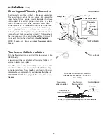
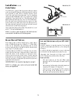
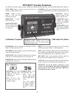
background image

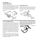
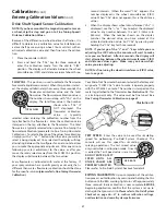
Tee “C”

Tee “A”

Pressure

Relief Valve

15

If you have a positive displacement pump or a cen trif u gal 

pump capable of generating excessive pressure, you must 

in stall a pressure relief valve and adjust it to a safe max i-

mum pressure. If a positive dis place ment pump is operated 

without a pressure relief valve, damage may re sult to pump 

or other plumbing component. 

See Illustration 7.

Range Adjust Valve

With oversized pumps, it may be necessary to install a range 

adjust valve. The range adjust valve will reduce the pump’s 

output to the rest of the system. Ad just ment of this valve is 

covered in the Pre-Field checkout, page 30. 

See Illustration 8.

Servo, Throttling Valves

The servo valve installs in an unrestricted return line to the 

inlet of the pump or directly into the tank. DO NOT install the 

servo valve closer than 12” to the flowmeter. The servo valve 

has a flow direction decal on it. Make certain that the actual 

flow direction matches the decal on the servo valve. Do not 

install the servo valve in the agitation line. Slow response 

time and marginal operation may result. The return line 

should tee from the main line just after the throttling valve. 

See Illustration 9.

 The throttling valve is used to limit the 

output (set maximum output) of the pump to the flowmeter 

and servo valve. The throttling valve is adjusted to put the 

servo valve in its optimal operating range. Please refer to 

Pre-Field System Checkout for proper valve adjustment 

procedure.
The servo valve connects directly to the main harness 3-pin 

W/P cable lead. If more length is required, use a 3-pin W/P 

extension cable of the appropriate length. 

If using a Braglia 

or other 12-volt control valve, please refer to 12-Volt Control 

Valve Calibration on page 38.

Tee “C”

Range

Adjust Valve

Tee “A”

Illustration 9

Illustration 7

Illustration 8

Installation 

(cont)

Pressure Relief Valve

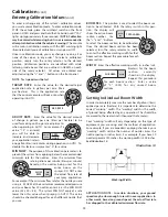
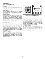
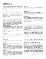
NOTE: The servo valve may be installed in the main spray 

line. For in-line installations, you will need to cut the servo 

cable and reverse the wires. Connect the RED wire to the 

BLACK wire and vice versa. Failure to reverse the wires will 

result in the servo valve operating backwards.

Summary of Contents for MT-3405 LR F

Page 1: ...MT 3405 F LR AUTOMATIC RATE CONTROLLER REFERENCE MANUAL TM ...

Page 2: ...his manual and the actual components before beginning Following the procedures described in this manual will ensure proper per for mance and help avoid problems or questions once you are in the field This manual is written for the MT 3405 F Model MT34F 99 LR which may be used for either English or Metric mea sure ment Please read the manual carefully and follow the instructions as they apply to yo...

Page 3: ...s to extend the term of the foregoing warranty period should the Buyer return completed warranty registration information with dated proof of purchase to the Seller within one 1 year from the original date of purchase All conditions and limitations of said foregoing warranty except the term of said foregoing warranty shall apply Said term shall be extended to a total of three 3 years from the orig...

Page 4: ...alibration Values 18 22 23 Setting Individual Boom Width 18 Banding Application Calibration 21 Determining Wheel Circumference 21 Drive Shaft Speed Sensor Calibration 22 Care and Maintenance 23 Fine tuning Speed Distance Calibration Value 24 Fine tuning Flowmeter Calibration 25 Test Speed 26 Pre field System Checkout 26 27 Plumbing Overview Diagram 19 Operation 27 29 Console Switches and Buttons 2...

Page 5: ... 31 Flowmeter Assembly 35 Plumbing Guidelines 36 37 General 36 Pump Inlet 36 Agitation 36 Servo 36 Flowmeter 36 Pump 36 Valve Purpose and Adjustments 36 37 Tank Shut off Valve 36 Agitation Shut off Valve 36 Pressure Relief Valve 37 Range Adjust Valve 37 Throttle Valve 37 Relief Valve 37 12 Volt Servo Valve Calibration 38 Appendices 39 45 Appendix A Optional Speed Sensor Mounting Installation 39 41...

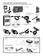
Page 6: ...ounting Bracket P N 10013 E Magnets 6 P N 12069 2 in hardware bag MT 3405 F LR AUTOMATIC RATE CONTROLLER REFERENCE MANUAL TM Reference Manual P N 13773 MT 3405 F Console P N 13775 10 10 Pin M P Extension Cable 6 P N 13221 5 3 Pin W P Extension Cable P N 10450 1 Electric Servo Valve P N 11218 14 Nylon Cable Ties P N 12910 FM750 GFN Flowmeter P N 11501 Console Mount Kit P N 13254 5 Hall effect Flow ...

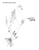
Page 7: ...7 MT 3405F System Layout Speed Boom 1 Yellow Boom 2 Brown Boom 3 Gray Aux Power Orange Gnd Gnd 12 VDC Boom 4 Black Boom 5 Red Fuse Holder and Terminals Installed by User Blue ...

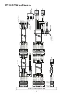
Page 8: ... RED 20 GA ORG 20 GA YEL 20 GA GRN 20 GA BLU 20 GA VIO 20 GA GRY 20 GA WHT 20 GA BLK 10 PIN M P 150 SHROUD 10 PIN M P 150 TOWER 120 IN 20 GA BRN 20 GA RED 20 GA ORG 20 GA YEL 20 GA GRN 20 GA BLU 20 GA VIO 20 GA GRY 20 GA WHT 20 GA BLK A B C D E F G H J K 10 PIN M P 150 SHROUD 10 PIN M P 150 TOWER A B C D E F G H J K 20 GA BRN 20 GA RED 20 GA ORG 20 GA YEL 20 GA GRN 20 GA BLU 20 GA VIO 20 GA GRY 20...

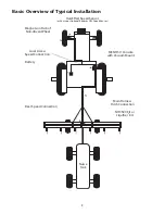
Page 9: ...ed Sensor or Vansco or Optional Radar or GPS Speed Sensor Magnets on Hub of Non driven Wheel Local Access Speed Connection Battery Rear Speed Connection Nurse Tank NH3500 Kit or Liquifier Kit TM Main Harness Hitch Connection MT NH3 II Console with Vacuum Mount ...

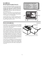
Page 10: ...nsole Connect the blue chassis ground wire to a good frame ground See Il lus tra tion 2 Make sure there is good metal to metal contact Route the power cable from the console to the battery Cut off excess length In routing cable to battery avoid ar eas where the ca ble may be subjected to abra sion or ex ces sive heat Install the in line fuse provided with the kit on the white wire as illustrated t...

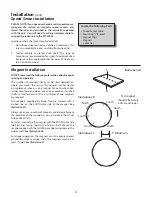
Page 11: ...ginformationaboutmagnet spacing and polarity The number of magnets that must be used depends on where you mount the sensor The general rule for tractor or implement wheels is one magnet for each wheel bolt minimum of two and always use an even number For drive shafts or small wheels ATV s a minimum of two magnets are required The magnets provided by Micro Trak are marked with a dashed line on the ...

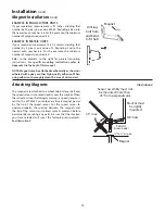
Page 12: ...other high quality adhesive When using adhesive thoroughly clean the area of dirt and oil Attaching Magnets The magnets are attached to a wheel hub or drive shaft and the speed sensor is mounted directly over the magnet When the wheel or drive shaft begins turning a speed impulse is sent to the MT 3405 F console every time a magnet passes by the tip of the speed sensor For the speed sensor to oper...

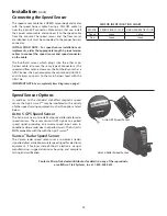
Page 13: ... Diagram on page 7 SENSOR IDENTIFICATION CHART SENSOR SENSOR BODY COLOR MAIN HARNESS TIE COLOR Speed Green Yellow Flow Green Green Vansco Radar Speed Sensor Speed Sensor Options In addition to the standard Hall effect magnetic speed sensor the Agri Cruise IITM may be interfaced with a va ri ety of other speed sensing equipment such as the options listed below Astro 5 GPS Speed Sensor The Astro 5 i...

Page 14: ...n 5 Flow Sensor Cable Installation With the flowmeter in place install the flow sensor cable GREEN body Screw sensor all the way into hole of flow me ter Tight en 3 8 jam nut to lock sen sor in place Uncoil flow sensor cable and carefully route it to meet the main harness flow connector marked with GREEN tie Align connectors and press firmly together until locking tab clicks into place Secure cabl...

Page 15: ...rvo valve Do not install the servo valve in the agitation line Slow response time and marginal operation may result The return line should tee from the main line just after the throttling valve See Illustration 9 The throttling valve is used to limit the output set maximum output of the pump to the flowmeter and servo valve The throttling valve is adjusted to put the servo valve in its optimal ope...

Page 16: ...Illustration 10 as your pattern for proper installation if your relief valve has a flow through port DO NOT install the relief valve closer than 12 to the flowmeter With the relief valve installed locate the violet wire tied back on flow servo cable and crimp a female terminal on the violet wire and connect to relief valve terminal Connect other terminal on relief valve to ground If your relief va...

Page 17: ... TOTALFLOW Displays total number of gallons liters applied May be reset CIRC Used in calibration mode to enter the circumference of the wheel that is equipped with the magnetic speed sensor Also used to calibrate Trak Star or radar speed sensors MIN FLOW Used in the calibration mode to enter the minimum flow rate GPM LPM of the spray boom FLOW CAL Usedincalibrationmodetoenterthecalibration value a...

Page 18: ...he display ap prox i mate ly 3 seconds You must be in HOLD to enter Cal In all Calibration Operations 1 Place the console in HOLD 2 Press and hold the CAL key for three sec onds to select the cal i bra tion mode The con sole dis play will read CAL and the red warn ing light will turn on 3 Turn the rotary dial to the desired CAL po si tion Then use the and keys to adjust the dis played val ue up or...

Page 19: ...er the effec tive work ing width for that boom section Re peat this pro ce dure for each boom section TARGET RATE APP RATE ADJUST RATE AREA HOUR BOOM SEL TOTAL AREA WIDTH Enter the effective working width in inches mil li me ters for the boom sec tion currently shown on the dis play Re peat this procedure for each boom sec tion Enter a value of 0 000 for any unused boom sec tions WIDTH SUB AREA Se...

Page 20: ... band is covering 40 percent of your total width 96 divided by 240 If you want to apply 20 GPA in the band enter 8 GPA as your target rate 40 percent of 20 GPA See Illustration 15 Illustration 15 WIDTH BOOM SELECT TEST SPEED ADJUST RATE TARGET RATE CIRC MIN FLOW FLOW CAL SPEED DISTANCE FLOW RATE TOTAL AREA APP RATE TOTAL FLOW SUB AREA ON OFF ON OFF 1 2 3 4 5 B O O M S RUN HOLD AREA HOUR CAL AUTO M...

Page 21: ...ter Enter the calibration value stamped on the tag attached to the flowmeter The total flow value is typ i cal ly selected when you are fine tuning the flowmeter cal i bra tion please refer to Fine Tuning Flow me ter Cal i bra tion To select either one of the values for calibration simply press the or button when the val ue you want to select is being displayed Once selected the display will stop ...

Page 22: ...is button will switch the control status of the system from fully automatic to manual control Each press of the button will change the status The display will show AUTO when automatic control mode is active and MAN when manual control mode is active Turn rotary dial to display desired readout CAL BUTTON This button allows you to enter and exit calibration mode Pressing and holding the CAL button f...

Page 23: ... system counters Operation cont Data Descriptions DISTANCE Displays the feet meters driven since the counter was last reset to zero This counter does not accumulate when the console is in HOLD This counter may be reset to zero independent of other system counters FLOW RATE Displays the actual gallons liters per minute being applied When the MT 3405 is used in conjunction with a Micro Trak NH3 cont...

Page 24: ...ng operation regardless of the position of the rotary switch When any of these counters reach their maximum capacity or when you want to start a new count the value in the register may be reset to zero by performing the following routine Counters may be reset independently of each other 1 Place the Run Hold switch in the HOLD position 2 Turn the rotary switch to the counter position to be reset 3 ...

Page 25: ...splay reads slightly higher 5 to 10 than the desired ap pli ca tion rate If the throttle valve is more than two thirds closed install range valve and perform pre field again 2 Now is a good time to confirm that GPA GPM MPH WIDTH and PSI all coincide with the nozzle man u fac tur er s charts PSI may be slightly higher than indicated by the charts due to pressure drop across the boom valves nozzle d...

Page 26: ...so check cable for breaks or incomplete connection If the flowmeter is new or has not been used for a long period of time the turbine may be sticky Flushing the system out with water should make the turbine spin freely Flow rate may be too low to register a reading or foreign material may be lodged in the flowmeter Troubleshooting General TOTAL LIQUID USED IS INACCURATE This may result from an inc...

Page 27: ...ffect sensor cable Holding the tip of the sensor up to the north pole of a magnet should result in a very high re sis tance in fi nite while holding the tip of the sensor up to the south pole of a magnet should result in a very low resistance near zero Troubleshooting Checking Individual Components TRAK STAR ULTRASONIC SPEED SENSOR Make certain that the Trak Star is emitting a crackling sound If n...

Page 28: ...eck from a good frame ground to each of the servo wires on the main harness connector Harness must be disconnected from servo valve You should get zero volts on each wire Holding the button should cause the RED wire on the three pin connector VIOLET wire on ten pin connector to pulse toward twelve volts and the BLACK wire on the three pin connector GRAY wire on ten pin connector should remain at z...

Page 29: ...ief Valves Larger Hoses Reduce Agitation Adjust Pressure Fluctuates in MAN Throttle and or Range Adjust Valve Adjust Pressure Speed and Spray Rate don not check out According to Tip Charts Inaccurate Pressure Reading Dirty or Worn Tips Usa a Different Gauge Check Each Boom Clean or Replace Pressure Always Goes too High in AUTO Minimum Flow Rate too High Re calibrate Pressure Fluctuates in AUTO Sag...

Page 30: ...se between tee B and the servo can usually be 3 4 but 1 will also work The hose between the servo and tee C should be at least as large as the servo If these lines are too small you may experience little or no pressure adjustment FLOWMETER The line feeding the flowmeter and the boom shut off valves should be at least as large as the flowmeter The size of lines going from the shut off valves to eac...

Page 31: ...he system The setting of the range adjust valve is determined by the throttle valve Start with the range valve fully closed and perform the Pre field Preparation System Checkout on page 25 If the throttle valve needs to be more than two thirds closed open the Range valve slightly and perform the Pre field Checkout again See Illustration 21 on page 32 Plumbing Guidelines cont Valve Purpose and Adju...

Page 32: ...Tee A Pressure Relief Valve Servo Valve Relief Valve Tee B MT 3405F Plumbing Overview Diagram cont For Oversized Pumps Illustration 21 For Positive Displacement Pumps Illustration 22 If Optional Relief Valve Kit is Used Illustration 23 32 ...

Page 33: ...33 Appendices ...

Page 34: ...hange position to the hub when the wheels are turned If the L bracket provided cannot be bent and mounted to properly position the sensor make a bracket similar to the one shown at right 3 Insert sensor adjust spacing and secure with 3 8 locking nuts 34 Speed Sensor and Bracket Bolts Lockwashers and Nuts Speed Sensor Cable Tie Cable Tie Speed Sensor Tap thread for bolts or weld FABRICATED BRACKET ...

Page 35: ...a ble tie around shaft and magnets Position each mag net so that its longest dimension moves in the di rec tion of rotation Pull cable tie tight and trim off excess An adjust able non magnetic stain less steel band clamp may also be substituted Appendix A cont Optional Speed Sensor Mounting on Drive Shaft Transmission Transfer Case Drive Shaft Magnets Positioned 180 Apart to 6mm to 13mm Spacing Se...

Page 36: ...nd safe area and continue with this procedure 4 With the rotary dial still at DISTANCE CIRC press and hold the CAL key for three seconds Once the con sole is in CAL the display will alternate be tween the cir cum fer ence value and the distance measured at about three second intervals When the word CAL appears the num ber dis played is the wheel circumference CIRC value When CAL does not appear th...

Page 37: ...d intervals between the flow me ter calibration value and the TOTAL FLOW value To tell which is which watch for the word CAL on display It will be present with the flowmeter cal i bra tion value but not with the TOTAL FLOW value 7 When the TOTAL FLOW value is displayed use the or button to adjust the value to match the amount of water run NOTE Once a value has been selected for ad just ment the di...

Page 38: ...hen the shaft is worn to the point of drag the turbine must be replaced NOTE The turbines have magnets built into the fins There are no visible magnets On a flat surface place each housing half on end Set and spin the turbine in each half It should spin freely If it does not spin freely remove the turbine wipe the shaft and try again If is still does not spin freely the shaft or bearings may have ...

Page 39: ...tions 12 volts Valve Switching Wire Ground Valve Switching Wire 12 volts Ground Relay Relay Motor Motor Basic 3 4 wire configurations are shown below If you need assistance for wiring other than shown contact Micro Trak for wiring instructions ...

Page 40: ... pressing and holding the CAL button until the RED light turns off approximately three seconds The console will remain in the special 12 volt control driver mode even when power is turned off Press and hold during power up v indicates 12 volt control valve driver Appendix F 12 Volt Servo Valve Control Valve Calibration NOTE Do not operate system with Micro Trak Electric Servo Valve installed when ...

Page 41: ...ters 3 28 feet meters 1 09 yards kilometers 62 miles LAND MEASUREMENT square millimeters 0 00155 square inches square meters 10 764 square feet square meters 1 195 square yards hectares 2 47 acres square kilometers 0 386 square miles LIQUID MEASUREMENT milliliters 0 034 fluid ounces liters 0 529 pint liters 0 264 quart liters 2 64 gallons VOLUME cubic meters 35 314 cubic feet cubic meters 1 307 cu...

Page 42: ...750 SS Flowmeter 14318 Power and Boom Console Harness Boom 120 Harness 240 14320 Flow Servo Run Hold and Boom 6 Harness 120 14319 Boom Branch Harness Booms 1 5 120 14324 Bulkhead Speed Cable 36 14793 Optional Run Hold Adapter Optional 2 Pin 3 Pin and 10 Pin Metri Pack 150 extension cables The Console Mount Kit is available only as a kit some parts are not available in individual components Parts a...

Page 43: ... B C A B RED WHT BLK RED WHT BLK RED WHT BLK RED BLK A B C 3 PIN W P 150 SHROUD RED ORG YEL GRN BLU VIO GRY WHT BLK BRN A B C D E F G H J K A B C D E F G H J K 10 PIN METRI PACK TOWER 10 PIN METRI PACK SHROUD RED ORG YEL GRN BLU VIO GRY WHT BLK BRN A B C D E F G H J K A B C D E F G H J K 10 PIN METRI PACK SHROUD 10 PIN METRI PACK TOWER RED N C RED BLK BLK RED BLK N C N C N C A B 2 PIN M P 150 SHRO...

Page 44: ... U S A by 111 East LeRay Ave Box 99 Eagle Lake MN 56024 0099 Toll Free 800 328 9613 507 257 3600 Fax 507 257 3001 www micro trak com trakmail micro trak com Printed in U S A 2004 Micro Trak Systems Inc P N 13773 Rev 2 ...

Reviews: