VDL S7‑300 U
Ser
M
anUaL
8
M
icro
‑A
ide
2
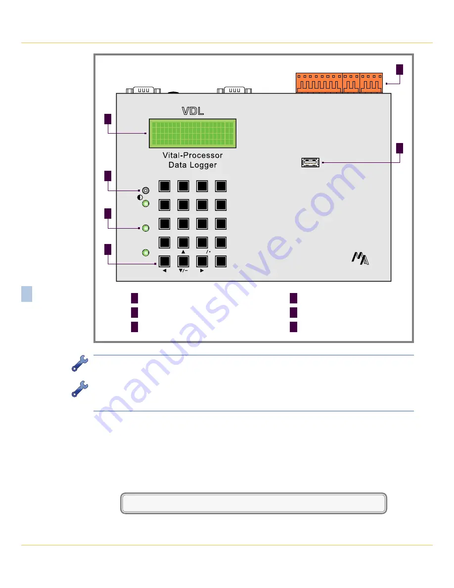
Figure 1: Typical Installation ‑ Front Panel View
T I M E
D A T E
1 6 : 2 0 : 5 9
0 2 - 2 0 - 1 4
S 7 - 3 0 0 D a t a L o g g e r
C O V I N A _ A R R O W G R A N D 9 . 7
Modem
Terminal
Power
Adj.
Save
USB
Flash Drive
1
2
3
Browse
4
5
6
Alpha
7
8
9
Setup
0
Esc
Enter
Save
M
ICRO
-A
IDE
20-positon keypad
F
LED indicators (3)
E
LCD contrast adjustment
D
USB Host Port
C
80-character LCD
B
Detachable tension clamp connectors (3)
A
F
E
D
C
B
A
To use the logger’s USB Device Port the proper drivers must be installed in the PC.
Appendix C
de‑
scribes how to locate and install the correct drivers.
The factory default setting for the Terminal Port is 38,400 Baud. Refer to the procedure entitled
“Terminal
Port Baud Rate” on page 21
for details on changing the Baud rate. The VDL requires 8 data bits, no
parity and 1 stop bit (i.e., 8‑N‑1).
3. Set the PC to emulate an ANSI terminal. In the case of HyperTerminal, click on the File, Properties
command. Select the Settings tab. Enable Terminal keys. Select ANSI from the Emulation drop‑down
list box.
4. Apply power to the PC. Ensure that the communications program is set for a direct connection to the
appropriate communications port.
5. Apply power to the VDL. The Liquid Crystal Display (LCD) panel should illuminate. The PC will display
the following message (Terminal Port).
Micro-Aide CWR-24E Flash Boot Loader 1.01
Press ESC for boot loader
Summary of Contents for CWR-24E
Page 2: ......
Page 14: ...VDL S7 300 User Manual 6 Micro Aide 1 User Notes ...
Page 22: ...VDL S7 300 User Manual 14 Micro Aide 2 User Notes ...
Page 96: ...VDL S7 300 User Manual 88 Micro Aide A User Notes ...
Page 98: ...VDL S7 300 User Manual 90 Micro Aide B User Notes ...
Page 106: ...VDL S7 300 User Manual 98 Micro Aide C User Notes ...


