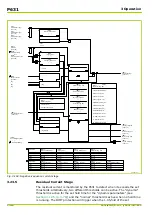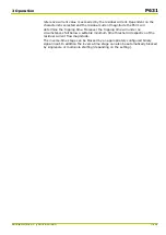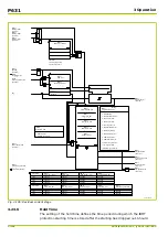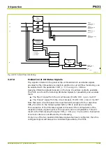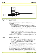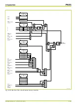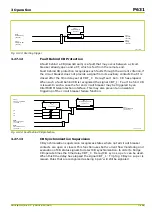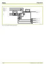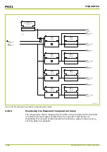
transient event. On the other hand, instantaneous signals are used to block or
restrain the differential protection functions as fast as possible:
●
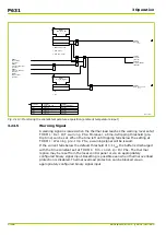
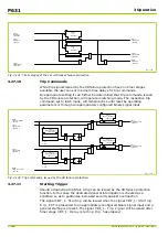
As soon as a CTS condition is detected (CTS: Idiff>(CTS)active is
present), the function will raise the differential protection low set threshold
to the DIFF: Idiff>(CTS) PSx setting; see
.
The setting for this value determines the CTS operating mode:
■
Signaling only:
DIFF: Idiff>(CTS) PSx = DIFF: Idiff> PSx. Differential protection
remains unrestricted, but there is a risk of unwanted tripping occurring
under load current.
■
Restricted operation:
DIFF: Idiff>(CTS) PSx = maximum load current. This will permit the
safe differential protection behavior, even during CT failure. There will be
no unwanted trip under any load condition, but protection will remain
operational for internal faults with currents exceeding the load current.
■
Blocking:
DIFF: Idiff>(CTS) PSx = DIFF: Idiff>> PSx. In practice differential
protection is blocked for all currents under normal operating conditions.
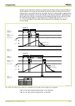
1
2
3
1
0
I
diff
I
R
Load line
for single side infeed
I
diff
>
I
R,m2
m
1
m
2
I
diff
>(CTS)
64Z6030A_EN
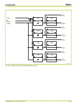
Fig. 3-120: Modification of the differential protection triggering characteristic with CTS active
3.25.6
Reset
Latched CTS signals can be reset using control parameters or through an
appropriately configured binary signal input as well as by a general reset
command.
3.25.7
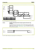
Multiple Signaling from the CTS Function
The signals issued by the CTS function (and/or measuring circuit monitoring, see
) are combined into the MAIN: Meas. circ.I faulty
signal. A signal is simultaneously issued by the self-monitoring function.
P631
3 Operation
3-154
P631/EN M/R-11-C // P631-310-650
Summary of Contents for P631
Page 2: ......
Page 4: ......
Page 7: ...Changes after going to press...
Page 8: ......
Page 16: ...P631 Table of Contents 8 P631 EN M R 11 C P631 310 650...
Page 56: ...P631 2 Technical Data 2 28 P631 EN M R 11 C P631 310 650...
Page 236: ...P631 3 Operation 3 180 P631 EN M R 11 C P631 310 650...
Page 246: ...P631 4 Design 4 10 P631 EN M R 11 C P631 310 650...
Page 266: ...P631 5 Installation and Connection 5 20 P631 EN M R 11 C P631 310 650...
Page 276: ...6 8 Configurable Function Keys P631 6 Local Control HMI 6 10 P631 EN M R 11 C P631 310 650...
Page 548: ...P631 10 Commissioning 10 10 P631 EN M R 11 C P631 310 650...
Page 568: ...P631 12 Maintenance 12 8 P631 EN M R 11 C P631 310 650...
Page 570: ...P631 13 Storage 13 2 P631 EN M R 11 C P631 310 650...
Page 572: ...P631 14 Accessories and Spare Parts 14 2 P631 EN M R 11 C P631 310 650...
Page 576: ...P631 15 Order Information 15 4 P631 EN M R 11 C P631 310 650...
Page 582: ...P631 A2 Internal Signals A2 4 P631 EN M R 11 C P631 310 650...
Page 608: ...P631 A4 Telecontrol Interfaces A4 18 P631 EN M R 11 C P631 310 650...
Page 637: ......

