MHS Boilers Alpha Jetstream MD Installation And User Manual Download Page 10

Water 

The system design must ensure a flow rate consistant with the output of the boiler at

Circulation

a temperature rise not normally exceeding 20ºC (25ºC Max).

System

Due to the Jetstream technology employed in the boiler, the boiler may be operated at 
continuous low return water temperatures without condensation and without the need for
back-end temperature protection measures, providing the minimum temperature limits 
detailed in the technical data are observed. This allows variable flow temperatures to be 
utilised (direct-on-boiler weather compensation) without the need for variable temperature 
mixing valves. This simplifies the installation and ensures peak operational efficiency from
the boiler.
Should the system be operated at temperatures below than those mentioned above,  
then a thermostatically controlled pumped by-pass (shunt pump) should installed
between the flow and return pipes to raise the temperature of the return water.
This is particularly important when firing with gas because of the higher dewpoint 
 temperature of gas products of combustion.

Water levels should be checked regularly and any leakages corrected in order to keep 
system water make-up to a minimum, because excessive make-up will lead to scale 
deposits forming in the boiler waterways causing local overheating and damage to the 
boiler sections. Where there is doubt as to the quantity of water make-up, a water meter 
should be fitted. If a system is known to lose water continuously, or be heavily
contaminated with dirt or sludge, then consideration should be given to installing a plate 
 type heat exchanger to separate the boiler from the damaging effects of the old system.

Boiler water systems should be thoroughly flushed and cleaned before a new boiler is
installed and system water should be treated with a scale and corrosion inhibitor
and best practise observed. The system should include strainers and consideration should
be given to fitting sludge traps if conditions warrant them.

The system can be either open vented or pressurised.The system must be fitted with 
appropriately sized safety relief valve, reference to BS5410 Part2 or BS6644 will give 

Safety of

guidance on selection.If the system is open vented then an appropriately sized open pipe 

water

must be installed from the flow pipe adjacent to the boiler to run by the shortest possible

circulation

direct route to terminate over the feed and expansion cistern. The boiler flow and return

system

pipes should be fitted with isolation valves taking care to ensure that the safety relief 
valve is installed onto the flow pipe between the boiler flow connection and the flow 
isolation valve.
An altitude guage should be installed onto the flow pipe at the same level as the top of 
of the boiler and marked with the minimum water level/pressure following first filling
of the system.

In the case of a sealed and pressurised heating system, an appropriately sized and 
charged expansion vessel should be installed in conjunction with an automatic
water make up unit (pressurisation unit).

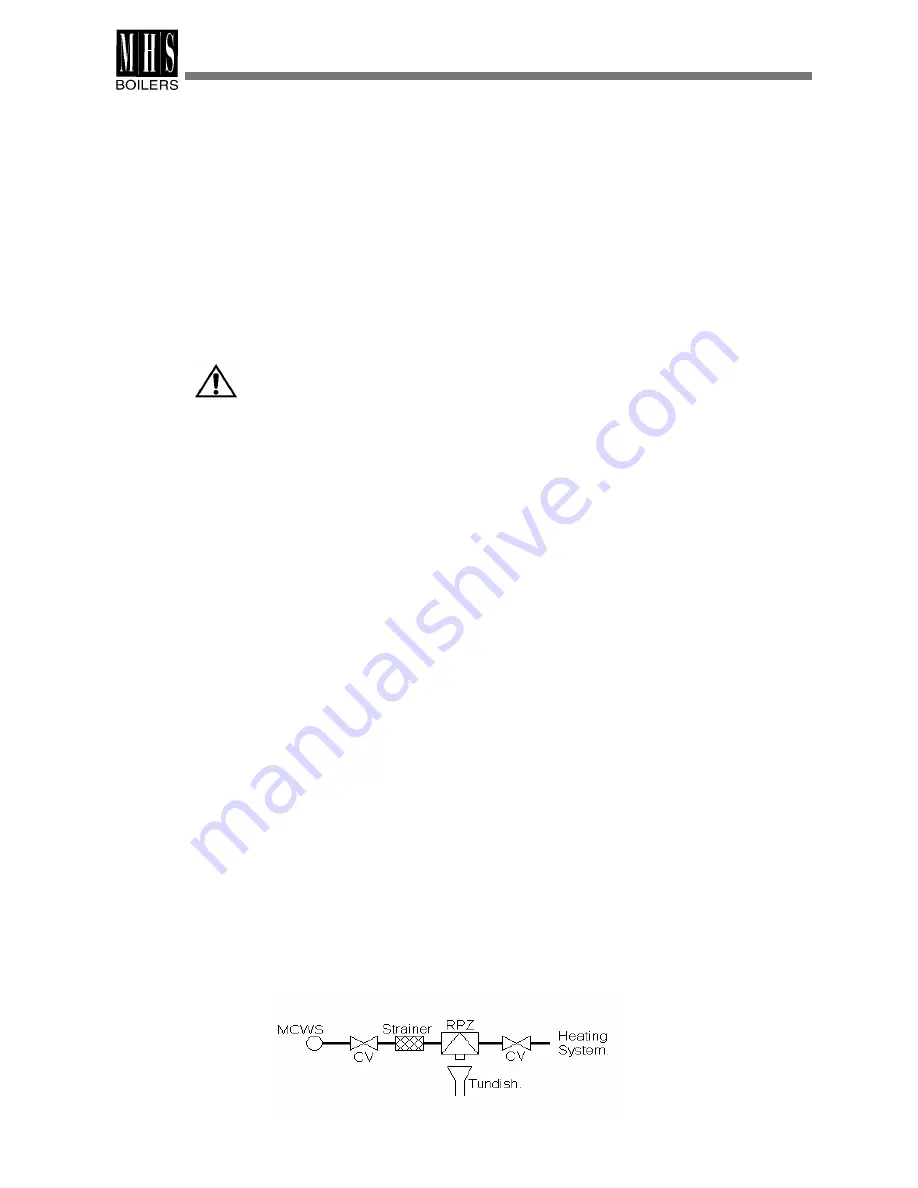
Filling the System . Non Domestic (other than in-house) fluid category 4

For category 4 systems, the approved method of filling must comprise the following
components arranged as shown: Control valve on the mains cold water pipework,
Strainer,Verifiable backflow prevention device with Reduced Pressure Zone (RPZ valve)
incorporating a type BA air gap, Tundish, Control valve on heating system.

PREPARATIONS BEFORE ASSEMBLY

Summary of Contents for Alpha Jetstream MD

Page 1: ...Assembly Operating and Maintenance Instructions Installation and User Guide Alpha Jetstream MD Cast Iron Boiler 105 300 kW 35 Nobel Square Basildon Essex SS13 1LT 01268 591010 01268 724064 01 07 04...

Page 2: ...requiremets of EN 303 1 Heating boilers with forced draught burners Terminology general requirements testing and marking EN 303 2 Heating boilers Part 2 Heating boilers with forced draught burners Spe...

Page 3: ......

Page 4: ...1012 1146 1280 1414 Burner mounting diameter mm 170 dimensions depth mm 115 Return flow connections DN 65 2 BSP M Flue gas temperature o C 185 Flue connection diameter mm 208 Weight boiler block kg 4...

Page 5: ...ion pipe This injection results in a pressure drop at the end of the pipe creating a vacuum This vacuum sucks hot delivery water of the rear section sections down to mix with the return water thereby...

Page 6: ...to average boiler water temperature of 70 C Flue gas temperatures Values given according to average boiler water temperature 70 C ambient temperature 20 C TECHNICAL INFORMATION Flue gas resistance mba...

Page 7: ...lable An existing service pipe must not be used without prior consultation with the local gas supply authority and the supply must be made through a suitable meter The matching of burner model burner...

Page 8: ...uld installation not support the weight of chimney The draft generated by the chimney should be capable of overcoming the chimney resistance Chimney calculations should be carried out in compliance wi...

Page 9: ...as appropriate Never drain the system unnecessarily Follow instructions for periodic cleaning and maintenance operations whose procedures are given further in this manual The boilers must be installed...

Page 10: ...e damaging effects of the old system Boiler water systems should be thoroughly flushed and cleaned before a new boiler is installed and system water should be treated with a scale and corrosion inhibi...

Page 11: ......

Page 12: ...litres of water We strongly recommend that the system is chemically cleaned and then dosed with a good quality corrosion and scale inhibitor before the boiler is first fired The boiler is guaranteed...

Page 13: ...ion chamber insulation are mounted on the rear section at the factory Smokehood is fixed to rear section Boiler block contains the materials used in the assembly of the block such as nipples fiberglas...

Page 14: ...described above Place rear section at the end of baseframes With its unroped side facing towards the rear fit the intermediate section squarely onto nipples of the rear section and secure by using a w...

Page 15: ...to one of the globe valves on test flange fitted to return connection Fill the boiler with water by connecting the other valve on test flange to the water circuit Meanwhile release the air left in th...

Page 16: ...ock the studs into the corner positions of rear section When placing the distribution pipe into the return connection ensure that the white arrow on the flange of the pipe points upwards The axis of t...

Page 17: ...bladed modules 95 and 99 The modules are combined together according to following table for preparing second pass retarders Retarders are placed into second and third flue gas passages of boiler as sh...

Page 18: ...return folds of the casing hanging the front edges of casing onto the upper casing support 155 and fixing the front lower end of the casing to the free end of the lower staybolt 7 Fit side casings by...

Page 19: ...anel making sure that cables are on the top side of the insulation Make electrical connections in accordance with Mandatory Regulations and Codes of Practice and follow burner manufacturers instructio...

Page 20: ...ASSEMBLY INSTRUCTIONS...

Page 21: ...tified The Alpha Jetstream MD Boiler must only be commissioned and serviced by competant Pre firing checks persons of approved classes qualified and certified to undertake the works involved i e Corgi...

Page 22: ...Prepare the cleaning brush combining items 101 and 102 Remove any deposits from combustion chamber and flue gas passages using cleaning brush 3 Clean the retarders and check their condition replacing...

Page 23: ......

Page 24: ...The boiler should start automatically failure when the electircity is restored Boiler If the burner does not operate check that there is enough fuel in the tank and the gate operational valve at the...

Page 25: ...EXPLODED DRAWINGS MD JETSTREAM EXPLODED DRAWING BOILER GROUP...

Page 26: ...EXPLODED DRAWINGS ALPHA JETSTREAM MD EXPLODED DRAWING INSULATION AND OUTER CASINGS...

Page 27: ...5 x Pmax 1 5 x Bars where Pmax is the maximum operating pressure of heating system for a duration of minutes and No leakage detected Leakages detected and corrected on following points 1 2 3 4 5 OTHE...

Page 28: ...A member of the Modular Heating Group Plc 35 Nobel Square Burnt Mills Industrial Estate Basildon Essex SS13 1LT Tel 01268 591010 Fax 01268 728202 www mhsboilers co uk...

Reviews: