Mhouse GD0 Installation Instructions And Warnings Download Page 22

22 Instructions GD0

The control unit contains a radio receiver for TX4 transmitters; the one
included in the package is pre-memorized and operative. If you wish to
memorize a new radio transmitter you have two choices:

• Mode 1: in this “mode” the radio transmitter is used to its fullest extent,
i.e. all the buttons execute a pre-established command (the transmitter
supplied with GD0 is memorized in Mode 1). It is obvious that in Mode 1
a radio transmitter can be used to command a single automation, i.e.:

• Mode 2: one of the four commands available can be associated to
each button. This mode, used properly, allows you to command 2 or
more different automations; for example:

Each transmitter is, of course, a separate unit, and while some are mem-
orized in mode 1 others can be memorized in mode 2 on the control unit.

The overall memory capacity is 150 units; memorization in mode 1 takes
up one unit for each transmitter while mode 2 takes up one unit for each
button.

Warning: since the memorization procedures are timed (10s), you
must read the instructions in the following paragraphs before you
proceed with their execution.

Button T1

“OPEN” command

Button T2

“Partial opening” command

Button T3

“Open only” command

Button T4

“Close only” command

Button T1

“Open only” command automation N° 1

Button T2

“Close only” command automation N° 1

Button T3

“OPEN” command automation N° 2

Button T4

“OPEN” command automation N° 3

5.4 

Memorization of Radio Transmitters

5.4.1 

Memorization Mode 1

1

Press button P1 [B] for at least 3s.

When the P1 LED [A] goes off, release the button.

2

Within 10s, press any button on the radio transmitter to be memorized

and hold it down for at least 3s.

If the memorization procedure is successful, the “P1” LED will flash 3
times. 

3

If there are other transmitters to be memorized, repeat step 2 within the

next 10s, otherwise the memorization stage will terminate automatically.

5.4.2 

Memorization Mode 2

With the memorization in mode 2 of the radio transmitter, any one of the
four commands (“OPEN”, “Open partially”, “Open only” and “Close only”)
can be associated to each button.

In Mode 2 each button requires a separate memorization stage.
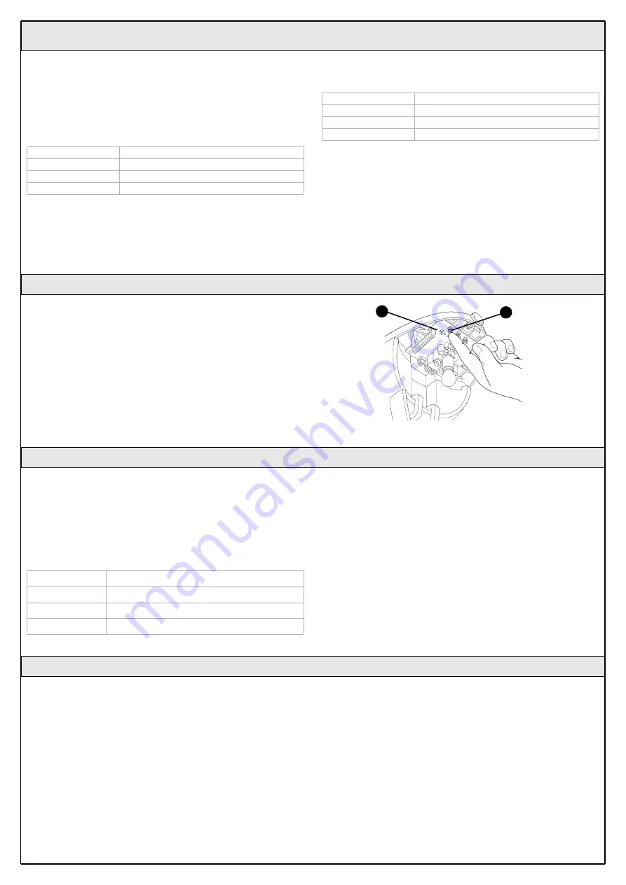
1

Press button P1 (figure 71) on the control unit as many times as the

number corresponding to the desired command, according to the fol-
lowing table:

2

Make sure that the P1 LED makes as many quick flashes as the num-

ber corresponding to the selected command.

3

Within 10 s, press the desired button on the radio transmitter to be

memorized, and hold it down for at least 2 s.

If the memorization procedure is successful, the “P1” LED will flash 3
times slowly.

4

If there are other transmitters to be memorized for the same type of

command, repeat step 3 within the next 10s, otherwise the memoriza-
tion stage will terminate automatically.

1 time

“OPEN” command

2 times

“Open partially” command

3 times

“Open only” command

4 times

“Close only” command

Figure 71

A

B

A new radio transmitter can be memorized in the control unit without
directly operating the buttons on it. You need to have an “OLD” pre-
memorized operational radio transmitter. The “NEW” radio transmitter to
be memorized will inherit the characteristics of the OLD one, i.e. if the
OLD radio transmitter was memorized in Mode 1, the NEW one will also
be memorized in Mode 1. In this case, during the memorization stage
you can press any key on the two transmitters. If, on the other hand, the
OLD transmitter was memorized in Mode 2 you must press the button
on the OLD transmitter which corresponds to the desired command, and
the button on the NEW transmitter to which you wish to associate that
command.

Holding the two transmitters, position yourself within the operating range
of the automation and perform the following operations:

1

Press the button on the NEW radio transmitter and hold it down for at

least 5s, then release it.

2

Press the button on the OLD radio transmitter 3 times slowly.

3

Press the button on the NEW radio transmitter once slowly.

At this point the NEW radio transmitter will be recognized by the control
unit and will assume the characteristics of the OLD one.

If there are other transmitters to be memorized, repeat all the steps
above for each new transmitter.

5.4.3 

Remote memorization

Summary of Contents for GD0

Page 1: ...Installation instructions and warnings English IST GD0 GB 4865 Rev 00 del 15 03 2005 MhouseKit GD0 For the automation of a sectional or overhead door...

Page 2: ......

Page 3: ...ent that liquid substances have penetrated inside the automation devices immediately disconnect the power supply and contact the MHOUSE customer service department The use of GD0 in these conditions c...

Page 4: ...stops E GD0K gearmotor 2 2 Description of the automation A B Figure 1 2 Product description 2 1 Applications GD0 is a set of components designed for the automation of sectional or overhead doors in re...

Page 5: ...of devices GD0K is an electromechanical gearmotor consisting of a 24V direct cur rent motor It features a mechanical release mechanism with cord that allows you to move the door manually in the event...

Page 6: ...nits The transmission of the command is confirmed by the LED A an eyelet B allows them to be hung on a keyring Figure 7 B A The pair of PH0 wall mounted photocells once they are connected to the contr...

Page 7: ...e guide and the brackets to the ceiling The head of the guide will have to bear all the strain of opening and closing the door the ceiling mounted brackets will have to bear all the weight of GD0 In b...

Page 8: ...m 7 2m2 max width max imum torque 55kg Overhead garage doors 240cm max height 270cm 6 48m2 max width maximum torque 55kg The shape of the door and the climatic conditions e g presence of strong wind m...

Page 9: ...ces refer to figure 13 you can start preparing the conduits for the electrical cables connecting the devices to the control unit The shock resistant conduits are designed to protect the electrical cab...

Page 10: ...and related washer as in fig 18 7 Hook the upper carriage E to the lower carriage C and place the entire carriage assembly inside the guide as in fig 19 8 Assemble the Guide B head as in fig 20 This...

Page 11: ...d lift the guide from the front and secure it with two screws anchors or riv ets depending on the type of surface 3 Secure the mounting brackets L using the screws M and nuts N and choosing the hole t...

Page 12: ...all the strain resulting from opening and clos ing the door 9 Loosen the screws in the two mechanical stops then place the front mechanical stop O before the carriage Figure 33 Push the carriage hard...

Page 13: ...he edge of the door With sectional doors the photocells can be mounted outside whereas with overhead doors they can only be mounted inside outside they would obstruct the movement of the door Point tr...

Page 14: ...the hole for the passage of the cables in the bottom or side depending on the installation position using a screwdriver 5 Mark the drilling points using the bottom as reference and make sure that the...

Page 15: ...ove the small piece of wire between ter minals 3 and 7 and make the connections as in Fig 56 if using the flashing light aerial remove the piece of wire which is con nected to terminal 2 and connect t...

Page 16: ...ly an external aerial can be used or the small piece of wire that is already connected to the terminal can be left which acts as an aerial 3 4 OPEN input for manoeuvre control devices Normally Open ty...

Page 17: ...t manoeuvres are not interrupted by any commands If the manoeuvres are not completed repeat the recognition procedure starting from step 1 The position recognition stage can be repeated at any time in...

Page 18: ...en carefully observed 2 Using the selector switch if provided or the radio transmitter test the opening and closing of the door and make sure that the door moves in the intended direction The test sho...

Page 19: ...directions provided in the corre sponding maintenance schedule 4 Maintenance 3 7 2 Commissioning The commissioning operations can be performed only after all the tests have been successfully carried...

Page 20: ...force OPEN function 1 Open Stop Close Stop Press button T2 once 2 Open Stop Close Open Press button T2 twice 3 Open Open Open Open opening only Press button T2 three times The following chapters descr...

Page 21: ...as described in the Photocell instructions in the event there are two pairs of photocells that could interfere with one another 5 3 2 STOP Input STOP is the input that causes the immediate interruptio...

Page 22: ...n partially Open only and Close only can be associated to each button In Mode 2 each button requires a separate memorization stage 1 Press button P1 figure 71 on the control unit as many times as the...

Page 23: ...ion stage or in case of failure Table 10 Symptoms probable cause and possible solution The radio transmitter does not emit any sig nal the LED A does not light up Check to see if the batteries are exh...

Page 24: ...s pause 2 flashes Triggering of a photocell At the starting of the manoeuvre one or more photocells do not enable it check to see if there are any obstacles If there is an obstacle impeding the movem...

Page 25: ...tion in progress On Memorization in Mode 1 This is normal during memorization in mode 1 which lasts maximum 10s Series of quick flashes from 1 to 4 Memorization in Mode 2 This is normal during memoriz...

Page 26: ...r 200W Insulation class 1 a safety grounding system is required Emergency power supply Flashing light output For visual signalling devices with 12V lamp maximum 21W Courtesy light 12V lamp maximum 21...

Page 27: ...ontrol units Lamp 12V 21W BA15 socket automotive type lamp Power supply contacts The device can only be connected to the FLASH output terminals 9 10 and ARIEL input 1 2 of the MHOUSE automation contro...

Page 28: ...Operating ambient temperature 20 50 C Use in acid saline or potentially explosive atmosphere No Protection class IP40 suitable for use indoors or in protected environments Dimensions weight 72 x 31 h...

Page 29: ...L of 9th March 1999 concerning radio equipment and telecommunications terminal equipment and mutual recognition of their conformity According to the following standards ETSI EN 300 220 3 ETSI EN 301 4...

Page 30: ......

Page 31: ...nufacture Location address Satisfies the essential requirements of the following Directives 98 37 EC Machine Directive 89 336 ECC Electromagnetic Compatibility Directive 73 23 ECC Low Voltage Directiv...

Page 32: ......

Page 33: ...control or key operated selector switch If the safety devices enable the operation the door will open normally otherwise actuate the control again within 3 seconds and keep it actuated 2 After approx...

Page 34: ...balanced door could cause injury If the range of the remote control is significantly diminished and the light emitted by the LED is feeble the remote control battery is probably exhausted The remote c...

Page 35: ......

Page 36: ...Mhouse Via Pezza Alta 13 Z I Rustign 31046 Oderzo TV Italia Tel 39 0422 20 21 09 Fax 39 0422 85 25 82 info mhouse biz www mhouse biz...

Reviews: