Instructions GD0 21
5.2
Optional Accessories
In addition to the devices featured in GD0, other ones are available as
optional accessories designed to enhance the automation system and
improve its safety and performances.
GA1:
OSCILLATING ARM accessory that enables the system to open
overhead-type doors
GU1:
MANUAL RELEASE KIT accessory that enables the manual open-
ing of the door even in the event of power failures.
For information on the new accessories, refer to the MHOUSE catalogue
or visit the site www.mhouse.biz.
5.3
Adding or Removing Devices
Devices can be added to or removed from the GD0 automation system
at any time.
Do not add any devices until you have made sure that they are
perfectly compatible with GD0; for further information contact
MHOUSE Customer Service.
5.3.1
Phototest output
This control unit is equipped with the “Phototest” function that increases
the reliability of the safety devices, making it possible to achieve “cate-
gory 2” according to the EN 954-1 (edit. 12/1998) regarding the control
unit and safety photocells.
Whenever a manoeuvre is begun, the relative safety devices are checked
and only if everything is in order will the manoeuvre start. If the test has
a negative outcome (photocell blinded by the sun, short-circuited cable
etc.), the fault is recognised and the manoeuvre is not performed.
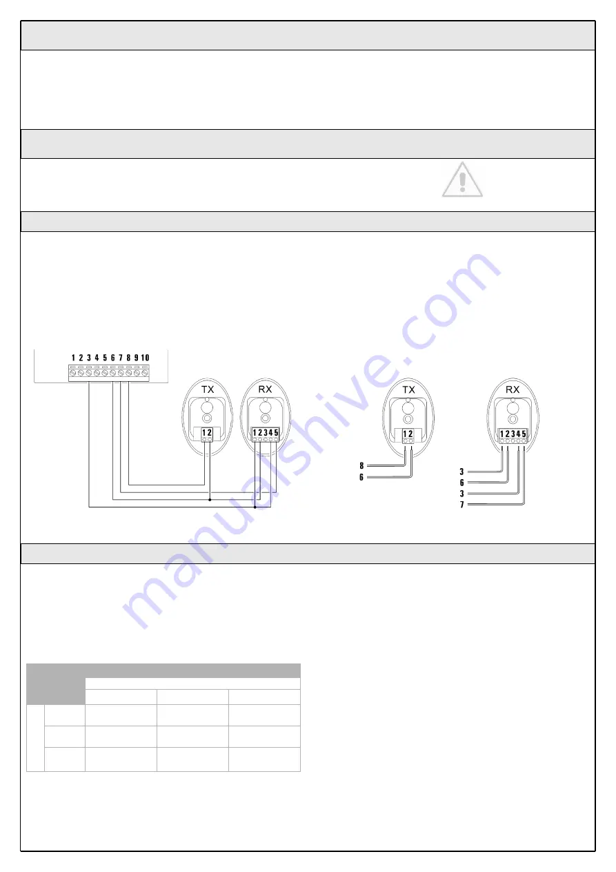
To add a pair of photocells, remove the jumper and connect as follows.
The photocell transmitter power is taken between terminals 8-6 of the
“Phototest” output and not from the services output. The maximum cur-
rent that can be used on the “Phototest” output is 100mA.
Activate the synchronism as described in the Photocell instructions, in
the event there are two pairs of photocells that could interfere with one
another.
5.3.2
STOP Input
STOP is the input that causes the immediate interruption of the manoeu-
vre (with a short reverse run). Devices with output featuring normally
open “NO” contacts (like the KS1 selector switch) and devices with nor-
mally closed “NC” contacts, as well as devices with 8.2K
Ω
constant
resistance output, like sensitive edges, can be connected to this input.
Multiple devices, even of different type, can be connected to the STOP
input if suitable arrangements are made.
To do this, proceed as described in the following table:
Note 1. The NO and NC combination can be obtained by placing the two
contacts in parallel, and placing in series to the NC contact an 8.2K
Ω
resistance (therefore, the combination of 3 devices is also possible: NO,
NC and 8.2K
Ω
).
Note 2. Any number of NO devices can be connected to each other in
parallel.
Note 3. Any number of NC devices can be connected to each other in
series.
Note 4. Only two devices with 8.2K
Ω
constant resistance output can be
connected in parallel; if needed, multiple devices must be connected “in
cascade” with a single 8.2K
Ω
termination resistance.
Warning: if the STOP input is used to connect devices with safe-
ty functions, only the devices with 8.2K
Ω
constant resistance out-
put guarantee the fail-safe category 3.
During the recognition stage of the opening and closing positions of the
door, the control unit recognizes the type of device connected to the
STOP input; subsequently it commands a STOP whenever a change
occurs in the recognized status.
Table 9
1
st
device type:
NO
NC
8,2k
Ω
2
nd
device type:
NO
In parallel
(note 2)
(note 1)
In parallel
NC
(note 1)
In series
(note 3)
In series
8,2k
Ω
In parallel
In series
not permitted
(note 4)
Figure 69
Figure 70


