background image

 
                                                                                                                                                   Pag. 

15

 a 

21      

A20H0019 


Wiring


Before  connecting  the  motor  to  the  power  supply,  it  is  necessary  to  connect  the  earth 
wire. This is accomplished by using the terminals, which are in the terminal box and on 
the motor frame. These terminals must be clean and protected from corrosion. 

Properly sized wires must be used, both to connect the motor to the power supply and to connect the 
earth  wire,  and  they  must  conform  to  all  applicable  norms  and  regulations.  It's  recommended  to 
follow the specifications stated in the EN 60204 standard. 
 
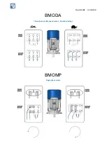
To connect the power supply, the wirings instructions here below  must be  followed exactly. For the 
wirings  of  those  single  speed  motors  destined  to  USA  and  Canada,  please  follow  up  the  additional 
instructions.  

After the  connection  is  completed,  check  thoroughly  the  tightening  of  the  terminals  nuts.  About  the 
wiring of the motors driven by an inverter, please follow up the inverter manufacturer instructions.  

For the connection of the auxiliary devices (such as thermal protectors, heaters, forced ventilation and 
so on) please consider the identification of the cables described in the relevant paragraph. 
 
For the connection of the auxiliary devices (such as thermal protectors, heaters, forced ventilation and 
so  on)  please  consider  the  identification  of  the  cables  Brake  coil  is  fed  through  a  rectifier  located 
inside the terminal box (except for the 24V DC brake).  

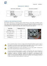
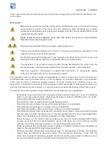
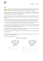
The AC side rectifier supply is stated on motor name plate. Rectifiers can be equipped either with type 
Q or type M. For connections, diagrams Q and M are to be followed.  

In the motors supplied with a 24VDC brake the rectifier is not supplied. In case of whatever difficulty 
please contact us. 

When switching the electromagnetic group on DC side it is useful to protect the contacts from burn 
out (RC device or free-wheeling diode)  

For any query, please contact us. 

Raddrizzatore M - Rectifier M 


Summary of Contents for BMO

Page 1: ...ratteristiche riportate sulla targa del motore sono garantite per installazioni in ambienti con temperatura compresa tra 15 C a 40 C e altitudine inferiore a 1000 metri s l m Informazioni generali sul...

Page 2: ...tezione IP che siano sostituiti con viti di medesimo passo e lunghezza Il motore deve essere installato in un locale areato lontano da fonti di calore e in posizione tale da consentire libera aspirazi...

Page 3: ...otore numero di avviamenti momento di inerzia applicato condizioni ambientali etc In generale si raccomanda di procedere alla prima ispezione dopo poche settimane di funzionamento e di stabilire conse...

Page 4: ...ora 137 Per facilitare le operazioni all estremit dell albero presente un esagono incassato o una spianatura che consentono di bloccare l albero con una chiave a brugola o con una chiave a forchetta U...

Page 5: ...rraggio dei dadi dei morsetti Per i motori comandati da inverter per il cablaggio attenersi alle indicazioni fornite dal costruttore di inverter Per l eventuale collegamento di dispositivi ausiliari p...

Page 6: ...ra potrebbero essere diversi da quanto indicato nella fotografia scelta come esempio La scaldiglia anticondensa pu essere alimentata solo dopo avere spento il motore Non deve essere alimentata durante...

Page 7: ...Pag 7 a 21 A20H0019 BMO BMXO Motore trifase a singola velocit BMOD Motore trifase a due velocit Dahlander...

Page 8: ...Pag 8 a 21 A20H0019 BMODA Motore trifase a due velocit Due avvolgimenti BMOMP Motore monofase...

Page 9: ...a recupero o eventuale smaltimento secondo specifiche modalit per contribuire ad evitare possibili effetti negativi sull ambiente e sulla salute e per favorire il reimpiego e o riciclo dei materiali...

Page 10: ...ressacavo 36 Scudo a flangia B5 37 Scudo a flangia B14 38 Rosetta elastica compensatrice 51 Chiave a T per rotazione albero a richiesta 71 Ventola 72 Anello elastico blocca ventola 76 Cuffia protezion...

Page 11: ...ial applications Performance and characteristics shown on the motor nameplate are guaranteed for installations in ambients having a temperature range between 15 C and 40 C at an altitude below 1000 m...

Page 12: ...nto their seats check that the cable inlet openings are tightly closed and that the terminal box screws are well tightened so that the protection level shown on the plate is respected The ringbolts if...

Page 13: ...ble to proceed to the first inspection after few weeks of working and to draw up a periodical maintenance plan Anyway it s recommended to provide inspections at least twice a year For specific informa...

Page 14: ...ing are present on the shaft allowing to lock the shaft with an allen key or with a fork wrench Once completed the operation please check again the air gap and if necessary repeat the operations Elect...

Page 15: ...iring of the motors driven by an inverter please follow up the inverter manufacturer instructions For the connection of the auxiliary devices such as thermal protectors heaters forced ventilation and...

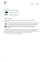
Page 16: ...e from what shown in the example picture The heater must be powered only after having turned off the motor Do not power the heater while the motor is running The presence of the forced ventilation ens...

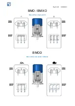
Page 17: ...Pag 17 a 21 A20H0019 BMO BMXO Three phase single speed motor BMOD Three phase double speed motor Dahlander...

Page 18: ...Pag 18 a 21 A20H0019 BMODA Three phase double speed motor Double windings BMOMP Single phase motor...

Page 19: ...separately from other waste and sent for recovery or possible disposal according to specific methods for avoiding possible negative effects on the environment and to health and for favoring its re us...

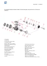
Page 20: ...erminal box 30 Terminal Box 32 Cable Gland 36 Flange B5 37 Flange B14 38 Elastic washer 51 Allen key for manual shaft rotation on request only 71 Fan 72 Fan Snap Ring 76 Fan Cover 81 Complete rotor 82...

Page 21: ...X 1 514 355 5199 email info mgmelectricmotors com http www mgmelectricmotors com USA UFFICI E DEPOSITO 269 Executive Drive Troy MI 48083 USA Phone 1 248 987 6572 Fax 1 248 987 6569 email info mgmelect...

Reviews: