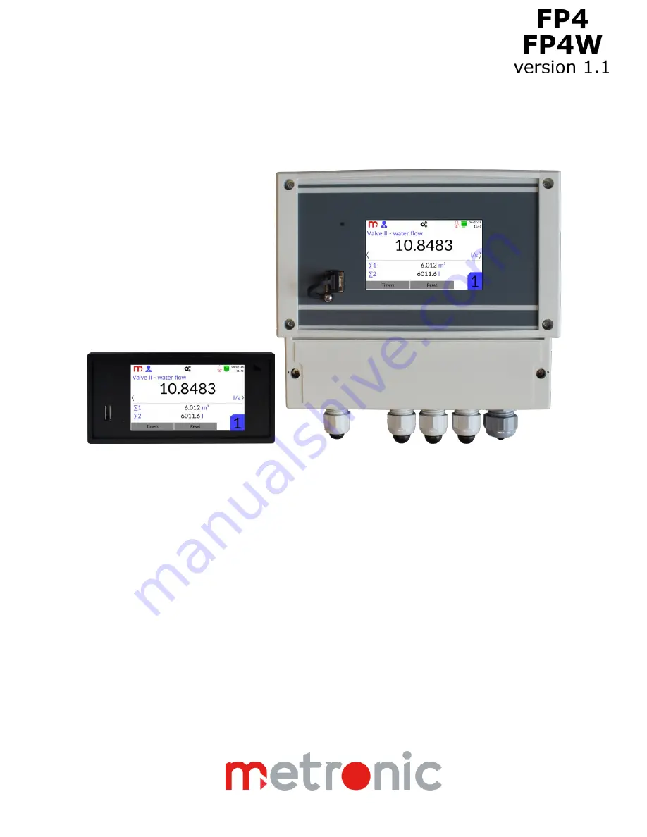
FP4, FP4W
Flow totalizer with data recording
OPERATING MANUAL
Version: 190226EN
This operating manual is also available on the CD-ROM.
Page 1: ...FP4 FP4W Flow totalizer with data recording OPERATING MANUAL Version 190226EN This operating manual is also available on the CD ROM ...
Page 2: ...ll the instructions especially those concerned with Environment Health and Safety EHS The device has been manufactured according to the requirements of relevant EU directives These instructions must be stored in a safe place near the installation of the device at all times All functions of the recorder are subject of modifications for the benefit of technical progress ...
Page 3: ...e 15 5 1 1 Configuration of jumpers related to analogue inputs IN1 IN2 16 5 1 2 Configuration of jumpers related to PULS type inputs IN3 IN4 16 5 2 Wiring transducers to analogue inputs 17 5 3 Wiring transducers to PULS type inputs 18 5 4 Wiring diagram for the analogue output 21 5 5 Wiring diagram for the relay outputs 21 5 6 Connection of RS 485 data transmission line 21 5 7 Ethernet port 22 5 8...
Page 4: ...5 Output window 39 10 6 Main Menu 40 11 PROGRAMMING SETTINGS 41 11 1 General settings 41 11 1 1 General 41 11 1 2 Display 42 11 1 3 Date Time 42 11 1 4 Service 43 11 2 Input and output settings I O 43 11 2 1 Inputs 43 11 2 1 Outputs 44 11 3 Communication settings 44 11 3 1 Ethernet port 44 11 3 2 RS 485 port 45 11 4 Channels settings 45 11 4 1 Inputs 46 11 4 2 General 47 11 4 3 Totalizers 48 11 4 ...
Page 5: ...rver 54 13 ADDITIONAL FUNCTIONS 55 13 1 Additional channel functions 55 13 1 1 User characteristics 55 13 1 2 Copying channel settings 55 13 2 Print screen 56 13 3 Web server 56 13 4 Software for PC 59 13 4 1 FP4 Config 59 13 4 2 FP4 RP FP4RPplus 59 14 FAILURE SYMBOLS 61 15 MODBUS RTU MODBUS TCP TRANSMISSION PROTOCOL 62 15 1 General information 62 15 1 1 Data types 62 15 2 Registers addresses 62 S...
Page 6: ...rovide electrical safety Caution risk of electric shock Caution risk of danger refer to accompanying documentation Caution Electrostatic Discharge for sensitive circuit Do not touch or handle without proper electrostatic discharge precautions Important comments and information Warning This product is designed and manufactured to withstand the forces encountered during normal use Use of the product...
Page 7: ...vice is an Class A type instrument In a residential environment it may cause radio interference In such cases one can request to the users for appropriate measures to avoid it Intended use Check that the product is suitable for use with the application Determine the correct installation and physical situation Prior to installation of Metronic AKP products take into account any environmental limita...
Page 8: ...products require no maintenance beyond periodic battery replacement Expected battery life is 10 years after the expiry of which must be returned to the manufacturer for a replacement From time to time you should clean the casing with a dry soft cloth When cleaning do not use solvents or abrasives They may cause discoloration or scratch the surfaces of device Disposal The FP4 FP4W contains a batter...
Page 9: ...1 set Fixing clamp 2 pc Seal assembled between case and panel 1 pc A CD with the user instructions and configuration software 1 pc Quick start guide printed 1 pc Warranty Card 1 pc Certificate of Calibration 1 pc 2 2 Delivery content FP4W The FP4W flow totalizer 1 pc A CD with the user instructions and configuration software 1 pc Quick start guide printed 1 pc Warranty Card 1 pc Certificate of Cal...
Page 10: ... and two PULS type Each inputs is assigned to appropriate channel Math channels Within the math channels selected mathematical operations are available addition subtraction division and multiplication based on the measured values according to the formulas entered by the user There are two available math channels Flow measurement Each measurement input including binary inputs and each calculated va...
Page 11: ... Config exe enables device configuration using the computer The software is intuitive and has an interface which is very similar to the interface of the device The software can be installed on the computers with the MS Win operating system The REPORT software FP4 RP exe for archived data enables visualization and analysis using the computer The FP4 RPplus exe program enables online transfer of arc...
Page 12: ... of electrical connections it is recommended to leave an extra space of approx 30 mm behind the device When installing the device in the panel opening the seal between the housing frame and the panel have to be fitted After inserting the device into panel opening the fixing clamps should be latched on both side walls Next tighten the screws With the removable screw terminal block it is possible to...
Page 13: ... without cable glands 213 mm x 185 mm x 102 mm width x height x depth Fig 4 2 Assembly diagram of FP4W device The device cannot be exposed to direct heat generated by other equipment When assembled the operating device cannot be affected by interference from other components contacts power relays inverters ...
Page 14: ... rear panel of the device FP4 or spring terminals at the bottom of the device FP4W Maximum wires cross section area is 1 5 mm2 Both wire and cord cables can be used Wires should be stripped 8 mm to 10 mm at the end If cables with a larger cross section are used it is recommended to use an intermediate terminal block in the measurement cabinet between the facility wiring and the device Fig 5 1 Rear...
Page 15: ...move the rear plate of the device s housing FP4 or the front part of the housing FP4W Disassembly of the housing should be made solely by a trained personnel The rear panel of the FP4 device should not be draw out more than necessary to connect jumpers In the upper part of the FP4 housing there is a label showing the correct way of configuration of the jumpers inside the device and electrical conn...
Page 16: ...nfiguration of jumpers related to PULS type inputs IN3 IN4 INPUT 3 IN3 INPUT 4 IN4 Input to connect J31 J32 J33 J34 J41 J42 J43 J44 OC or passive contact type transmitter X X EH type current transmitter X X NAMUR type current transmitter X X active voltage transmitter Notes The X sign means closed jumper The device is delivered is the OC contact configuration the additional filtering capacitor dis...
Page 17: ... type passive transducers Fig 5 5 Wiring passive transducers to 0 4 20mA input type Terminal No FP4 Description Terminal No FP4W 1 4 24V OUT 22 mA max I Transducer power supply Each output is protected by resetable polymer 50 mA fuse Current loop signal input 21 24 2 A 5 A I Current loop signal input 22 A 25 A 3 B 6 B Not used 23 B 26 B 0 4 20mA input type active transducers Fig 5 6 Wiring active ...
Page 18: ...Fig 5 8 Wiring of transducers with voltage output Terminal No FP4 Description Terminal No FP4W 1 4 Not used 21 24 2 A 5 A U Voltage signal input 22 A 25 A 3 B 6 B U Voltage signal input 23 B 26 B 5 3 Wiring transducers to PULS type inputs The device has two PULS type inputs which can work in one of the selected modes OC contact EH NAMUR U It should be taken into account that configuration of jumpe...
Page 19: ...F U Input 16 F 19 F 9 F 12 F U Input 17 F 20 F Notes Input in OC contact configuration not requires external voltage source EH input type active current transmitter Fig 5 10 Wiring of current transmitters to PULS type inputs EH configuration Terminal No FP4 Description Terminal No FP4W 7 10 Not used 15 18 8 F 11 F I Current loop signal input 16 F 19 F 9 F 12 F I Current loop signal input 17 F 20 F...
Page 20: ...otected by resetable polymer 50 mA fuse Current loop signal input 15 18 8 F 11 F I Current loop signal input 16 F 19 F 9 F 12 F Not used 17 F 20 F U input type transducers with voltage output Fig 5 12 Wiring of voltage transmitters to PULS type inputs Terminal No FP4 Description Terminal No FP4W 7 10 Not used 15 18 8 F 11 F U Voltage signal input 16 F 19 F 9 F 12 F U Voltage signal input 17 F 20 F...
Page 21: ...nection of RS 485 data transmission line Fig 5 15 Wiring diagram for RS 485 Notes The device RS 485 receiver driver allows connection of up to 32 devices An RS485 MODBUS configuration must have one trunk cable along which devices are connected directly daisy chaining or by short derivation cables The maximum bus length depends on the baud rate the cable gauge capacitance or characteristic impedanc...
Page 22: ...the bottom of the FP4W device Outputs connections are compliant with EIA TIA 568A B A LAN cable Patch Cord ended with RJ 45 plug may be connected to this port 5 8 Power supply connection FP4 Fig 5 16 Power wiring diagram FP4 The device requires 24 VDC power supply If supplied from 230 110 VAC it is recommended to use high efficiency industrial switching power supply at minimum 15 W of delivered po...
Page 23: ... 5 17 Jumpers inside the FP4W device for changing the supply voltage Device supplied with 230 VAC source Fig 5 18 Configuration of jumpers in the FP4W device device supplied with 230 VAC source Fig 5 19 Power wiring diagram device supplied with 230 VAC source Fig 5 20 Diagram of wiring the power supply and I O signals to the FP4W device device supplied with 230 VAC source It is recommended to use ...
Page 24: ... O signals to the FP4W device device supplied with 24 VDC source If device is supplied from 24 VDC source it is recommended to use high efficiency industrial switching power supply at minimum 15 W of delivered power To ensure safety the device s supply must satisfy the conditions applicable to lower voltage sources SELV Safety Extra Low Voltage supplied with the 24 VDC as per the IEC60950 1 Detail...
Page 25: ... switching between windows and shows up the Main Menu icon on the title bar which enables switching to the settings window Additionally the front panel contains 3 USB port enables connecting an external mass storage device a USB flash memory to move data stored in the internal memory from the device to a PC 4 LED signals processes using colors green lights during taking a screenshot and when new a...
Page 26: ...larm status flashing illuminating icon indicates an alarm more information in section Alarms Archive status displayed icon informs that the archiving process is enabled more information in section Archive Date and time read from the RTC clock 6 1 2 Switching between windows Switching between windows is possible using arrows and To show up arrows touch the screen Fig 6 3 Touching the screen shows u...
Page 27: ...n Changing the password User The first level of the authorised user It enables viewing of the device settings archive control start stop new archive file resetting the values minimum and maximum zeroing the totalizers and copying the files through the USB port In addition user may take screenshots Administrator The second level of the authorised user It enables the same functions which has User le...
Page 28: ...r the User the access level No logged in user is automatically removed there is no possibility to log out from the User level In addition to the change of the password the Administrator can also change the User password without the need to know the previous password If the Administrator s password is forgotten contact the Metronic AKP Service 7 2 Change of the language To change the language in th...
Page 29: ...smission Ethernet tab configuration 9 Display display brightness background colour screen saver parameters Display tab configuration 10 Changing administrator password Change password After configuring and confirming the selection click on the Exit icon There will be a message with the request to confirm the intention to make changes Detailed information regarding programming of the individual set...
Page 30: ...d delete archive files from the device except for current archives Fig 7 1 An example view of the USB window To record the current archive files select the Save current archives to USB option As a result three archive files i e data totalizer and event files will be stored to the pendrvie If another file is to be recorded on a USB drive first select the relevant file from the list The selected fil...
Page 31: ...xt step select the button from the title bar and then the icon Select the Service tab and then the Restore Factory Settings button The device will automatically reboot with factory settings After choosing the factory settings option each device is activated in English by default to choose a language select General tab Language All previous settings will be lost in particular I O settings which res...
Page 32: ... 32 receivers transmitters Transmission protocol Modbus RTU Slave Transmission rate 1 2 2 4 4 8 9 6 19 2 38 4 57 6 115 2 kbps Parity control Even Odd None Frame 1 start bit 8 data bits 1 stop bit Maximum length of line 1200 m Internal terminating resistor Vcc A B G 390 Ω 220 Ω 390 Ω activated by DIP switches Maximum differntial voltage A B 7 12 V Minimum output signal of transmitter 1 5 V at RL 54...
Page 33: ...flammable plastic material Noryl Dimensions with connectors w X h X d 144 mm X 72 mm X 127 mm Dimensions of panel cut out w X h 138 1 mm X 68 0 7 mm Maximum panel thickness 5 mm Weight 0 5 kg Protection class IP30 on front panel side IP30 on rear panel side Mechanical Dimensions enclosure FP4W Enclosure type Wall mount polycarbonate material Dimensions w X h X d without cable glands 213 mm x 185 m...
Page 34: ...the 0 4 20mA configuration Configuration R RTD input Sensor type Resistive refer the table below Linear resistance Sensor connection type 2 wire Sensor current 420 μA Wire resistance compensation in the 2 wire connection User programmed in the range of 99 99 Ω Resistance of wires to the sensor max 50 Ω Transducer resistance range 0 2700 Ω Initial accuracy Ta 25 C 0 5 Ω typically 0 3 Ω Conversion c...
Page 35: ...urrent ca 4 3 mA Switch on off threshold ca 2 4 V 2 6 V Maximum short circuit resistance 100 Ω 5 The device is delivered in the OC contact configuration with the additional filtering capacitor disconnected Configuration current input EH Input resistance 200 Ω Switch on off threshold ca 11 mA 13 mA Configuration current input NAMUR Input resistance 1 5 kΩ Switch on off threshold ca 1 6 mA 1 8 mA Co...
Page 36: ...FP4 FP4W 36 9 ENTITY LAUNCHING THE PRODUCT ON EUROPEAN UNION MARKET Manufacturer METRONIC AKP s c st Żmujdzka 3 PL 31 426 Kraków Poland Tel 48 12 312 16 80 www metronic pl Vendor ...
Page 37: ...el channel description current value a unit values and units of totalizers 1 and 2 if totalizers are active values of timers operating time of totalizers 1 and 2 if totalizers are active channel number In the top part of the screen there is a channel description entered by the user Below the current value of the channel is displayed together with the unit declared by the user At the bottom part of...
Page 38: ...rchiving totalizers Additionally this field contains information concerning the percentage use of the internal memory of the device Below is the field containing information about the current archiving status of process values and totalizers for all channels in the order from the first to the sixth channel In the Process Values row one rectangle corresponds to one channel current value In the Tota...
Page 39: ...d Continuous displaying of the color means confirmed alarm Fig 10 4 An example view of the Alarms window Confirmation of alarms is done by pressing the button required access level User or higher 10 5 Output window The Output window contains the current statuses of all relay outputs and the analogue output This window is displayed only when at least one relay outputs or analogue output is enabled ...
Page 40: ...he Exit icon This screen contains a menu made up from the function icons and their descriptions Clicking on the pictogram toggles the user to a suitable sub screen with settings windows Login General I O Communication Channels Archive USB More information in section PROGRAMMING SETTINGS Switching to individual settings windows is possible only for the logged in user The settings can be saved from ...
Page 41: ...u window the icon on the title bar Clicking on the icon toggles the user to a suitable sub screen with settings windows Login General settings Input and output settings Communication settings Channels settings Archive settings USB 11 1 General settings Switching between settings windows is possible by using tabs General Display Date Time Service Confirm and cancel buttons are common for all sub wi...
Page 42: ...ime User can choose two screen saver levels 0 the screen goes black and 20 3 Setting the background color of the screen two colors to choose from white and black 4 Setting the idle time after the elapse of which the screen goes dimmed using slider for 0 min the screen will not be dimmed 11 1 3 Date Time Time field Enables the setting of time in the hour minute second format The changes are made us...
Page 43: ...to the Main Menu In the I O settings window only the hint regarding the correct connection of jumpers inside the device is displayed not their current configuration The symbol means shorted jumper the symbol means opened jumper Detailed information about the correct connection of jumpers is in the section Configuration of jumpers inside the device Fig 11 2 An example view of the Inputs and Outputs...
Page 44: ...s remain open in the event of power failure Analog output Source Channel 3 Disabled Channel 1 6 1 1 Selection the output mode as switched off or as a retransmission of the selected channel value in the form of 4 20mA current loop 4 20 mA span may be set as a sub range of retransmitted channel span by entering the process values for 4 mA and 20 mA respectively Failure value Disabled Disabled Consta...
Page 45: ...address assigned For more information on Modbus registers addresses and data format refer to section MODBUS RTU MODBUS TCP TRANSMISSION PROTOCOL 11 4 Channels settings The channel number is selected using the drop down list located in the upper left corner of the screen The description of the channel can be edited by clicking on the text in the Tag field Then the screen keyboard will pop up The ch...
Page 46: ...mber mode 2 Characteristic Linear Linear User 1 1 TEST State Impulse 3 1 Information about the channel type Measurement 2 Information about the set operating mode for the input assigned to the channel 3 For input in the Frequency operating mode the characteristic is typically set to Linear other setting options are also available for example User characteristic For input in the Impulse operating m...
Page 47: ... Archiving Disabled Disabled Enabled 5 Failure value Disabled Disabled Constant value 6 1 The unit is provided for information purposes only User can put in any text string which does not affect the calculated or measured results displayed by the device 2 The Time base is crucial only for flow measurements and totalizers calculation In spite of Unit set above it determines calculations for totaliz...
Page 48: ...e totalizer resets at 0 00 every day Weekly the totalizer resets at 0 00 every Monday Monthly the totalizer resets at 0 00 every first day of month 2 The unit is provided for reference purposes only User can enter any unit which does not affect the results displayed by the device 3 The multiplier allows multiplication of the measurement results by one of the three values selected from the list For...
Page 49: ...value is the difference between the threshold value exceedance and return to normal The threshold hysteresis value is entered in units of the measured value assigned to a specific measurement channel For example for a threshold set to High 48 C threshold level and 0 5 C hysteresis means that the threshold will be exceeded above 48 C and will return to normal below 47 5 C 48 0 5 For a threshold set...
Page 50: ...ing files are created in the daily weekly and monthly system Daily device creates new archive files at 0 00 every day Weekly device creates new archive files at 0 00 every Monday Monthly device creates new archive files at 0 00 every first day of month 2 The basic MAIN ARCHIVE time interval I Recording interval should correspond to the measurement process If the recording interval is too short the...
Page 51: ...ypes Data archive file name organization YYAXX csv Totalizer archive file name organization YYTXX csv Event archive file name organization YYEXX csv XX successive archive file number starts from 01 and ends at 99 If this number is exceeded the numbering is resumed from 01 YY device ID it is consistent with the user settings in case of change the ID a new file will be created Each archive is record...
Page 52: ...evice ID NUMBER OF ROW information about the number of rows in the header ARCHIVE TYPE archive type DATA process value archive EVENT event archive TOT totalizer archive CRC1 CRC control The process values archive and totalizers archive also has an additional archive header which contains information about set parameters selected channels description unit etc 12 6 1 Data archive Organization of add...
Page 53: ...ut summer 1 or winter 0 time enabled CHANNEL X TOTALIZER Y value of totalizer X channel number from 1 to 6 Y totalizer number 1 or 2 CHANNEL X TIMER Y the value of the timer which counts the operation time of totalizer 1 or 2 the value is in seconds X channel number from 1 to 6 Y timer number 1 or 2 CRC2 CRC control 12 6 3 Event archive Organization of records in the events archive file DATE TIME ...
Page 54: ...er xxxxx SYS LOGOUT Logout the user 12 7 Copying archive files from the device Copying archive files from the device is possible in two ways using a USB flash memory a USB stick or using an Ethernet connection and the device web server 12 7 1 Copying archive files to USB flash memory Connect the USB flash memory to the USB port in the front panel of the device Click on the icon from the title bar ...
Page 55: ...ct the Edit Point button Fig 13 1 An example view of the Channel settings window edition of user characteristics Two identical measurement values x cannot be entered for the same characteristic The entered data will be treated as erroneous and will be highlighted in red After entering the points for the characteristic confirm the willingness to make changes by pressing the button To cancel impleme...
Page 56: ...is resumed from 0 and the images are overwritten All files are saved in the bmp format To copy the image from the internal device memory to a connected USB flash memory use the icon from the title bar and then click on the icon Fig 13 2 Saving the print screen file Among the files situated in the window on the left side of the screen from the PRTSCR folder select the file to be copied folder is at...
Page 57: ...oose Results Tables Channels The table shows values for all channels counters and timers if they are enabled It should be taken into account that the page is not refreshed automatically To refresh data press the Refresh button at the bottom of the screen Fig 13 4 Web server Results Tables Channels The web server also shows the status of outputs in the device Results Tables Outputs if the analogue ...
Page 58: ...reshed automatically To refresh data press the Refresh button at the bottom of the screen Fig 13 5 Web server Outputs The list of archive files is in Archive tab The files are downloaded to the computer by clicking on the assigned archive name in the list of archive files It is possible to sort archive files by pressing on the name of the column header in the table Fig 13 6 Web server list of arch...
Page 59: ...ram is used for analysis and visualization of measurement results Depending of the archive type measurement results may be presented in a graph or in the table form In extended version FP4 RPplus exe there is possibility to download archive files from the device via Ethernet connection Detailed information is in instruction manual for the FP4 RP program Fig 13 8 An example window view in the FP4 R...
Page 60: ... FP4W 60 Fig 13 9 An example window view in the FP4 RP program data presented in a graph data archive Fig 13 10 An example window view in the FP4 RPplus program data presented in a table totalizer archive ...
Page 61: ...ot displayed W Wait value is not available symbol is displayed when the channel is connected to the input which has not been yet configured It is usually displayed in the beginning of the device operation Circuit break concerns only the current inputs set to 4 20mA mode E Value out of the range exceeded for the input R Value out of the range exceeded for the sensor ERR Measurement error due to rea...
Page 62: ... LByte 2 1 4 3 6 5 8 7 15 2 Registers addresses Process values are available in the floating point format as per IEEE 754 for the 32 bit digit type with the floating point and single precision 32 bit floating point single The totalizers are available in the floating point format as per IEEE 754 for the 64 bit digit type with the floating point and double precision 64 bit floating point double or i...
Page 63: ...3 300044 400044 44 4 64bit double 4 300048 400048 48 4 64bit double 5 300052 400052 52 4 64bit double 6 300056 400056 56 4 64bit double Addresses table of Timer 1 No measuring channel Register number Modbus address Size in registers 1 300060 400060 60 2 uint 32bit 2 300062 400062 62 2 uint 32bit 3 300064 400064 64 2 uint 32bit 4 300066 400066 66 2 uint 32bit 5 300068 400068 68 2 uint 32bit 6 30007...
Page 64: ...int 64bit 4 300096 400096 96 4 int 64bit 5 300100 400100 100 4 int 64bit 6 300104 400104 104 4 int 64bit Addresses table of Totalizer 2 int 64bit No measuring channel Register number Modbus address Size in registers 1 300108 400108 108 4 int 64bit 2 300112 400112 112 4 int 64bit 3 300116 400116 116 4 int 64bit 4 300120 400120 120 4 int 64bit 5 300124 400124 124 4 int 64bit 6 300128 400128 128 4 in...