


5-22
Ports E0 to E4 are connected to the switches on the control panel. These
are read 50 times per second. If a switch changes its status from off to
on, the program in the processor will execute the function that was
linked to the operation.
The LCD display is controlled through Port B via the LCD drivers IC2
and IC3. The processor's timer generates a 100Hz rectangular signal
(output A3), which drives the rear panel of the display. This signal can
be monitored at pin TP2. The processor controls three D/A converters.
Two of these are situated in IC8, while the third is situated in IC15. IC8
is loaded in parallel through Port C, with control signals at Port A 4-6.
IC15 is loaded in series, because this is easier when the signal is to be
led through optical connectors to obtain galvanic separation.
The A/D converter in the processor is used to monitor the current from
the battery. The voltage is reduced by resistors R2 and R3, and led to the
ND converter via port E5. The +5V power is used as a reference by the
ND converter at VRH.
IC-21 is a serial EEPROM, which is set aside for future use.
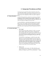
3.
Lead Test
The resistance between test plugs J4 and J5 is determined by measuring
the voltage drop over R4. The current from R4 is led to the processor in-
put E6 via resistor R88. If the power falls below the threshold internally
in the processor), the program in the processor will cause the display to
flash.
4.
Temperature Output
The temperature output comprises a 3-way slide switch with a resistance
array that simulates thermistors, which are used for measuring tempera-
tures. The resistances are precise and designed to give accurate values.
By varying the position of the switch, the ohm values for the 3 different
positions can be entered.
5.
ECG Outputs
The ECG waves are generated from matrices in the processor. The proc-
essor updates the 8-bit D/A converter in IC8 (channel A) 500 times per
second. IC-10 amplifies the signal and the amplitude is set by P4. P1 ad-
justs the amplification in the D/A converter. From pin 7 at IC10 (TP-8),
the ECG signal is led to the resistive power elements. These organize the
correct amplitude levels on all the ECG contacts. The output impedance
for 4 of the outputs can be set at 500 ohms or 1000 ohms by slide switch
SW7. The impedance can also be modulated at the LL or LA output, de-
pending on the position of slide switch SW6. Refer to section on respira-
tion.
IC19 sets the voltage reference level for the two D/A converters in IC8.
The reference voltage is amplified in the first half of the microprocessor
(IC1). The second half of the microprocessor is used to drive the high
level output for the ECG signal. The amplification is not adjustable.
Summary of Contents for PS-416M
Page 1: ...1 1 PS 416M User Service Manual PATIENT SIMULATOR...
Page 4: ...1 4 This page intentionally left blank...
Page 6: ...1 6 This page intentionally left blank...
Page 10: ...1 10 This page intentionally left blank...
Page 12: ...2 12 This page intentionally left blank...
Page 20: ...4 20 This page intentionally left blank...
Page 28: ...5 28 This page intentionally left blank...
Page 29: ...5 29 Component Location...
Page 30: ...5 30 Schematic Diagram Part 1...
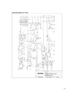
Page 31: ...5 31 Schematic Diagram Part 2...
Page 32: ...5 32 This page intentionally left blank...
Page 34: ...5 34 This page intentionally left blank...
Page 36: ...5 36...


