


3-15
sire to store several waveforms.
By using the left-hand key (tens),
you can switch between waveforms stored in the instrument.
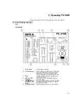
When the apparatus is switched on, the display will show the program
version for a short period before switching into standard mode.
Manual ECG, High Level Output
The high level ECG output signal is a Lead II waveform with 0.5V/mV
of low level Lead II. The high level ECG connection (standard phone
jack) is situated in the upper left-hand corner of the instrument.
Respiration
The respiration signal is transferred via ECG connections. The position
of the LEAD switch determines which lead is in use. The position of the
switch must correspond to the type of patient monitor being used. The
BASE (baseline impedance) switch sets the impedance between each
lead. The respiration parameter (breathing rate/min.) is selected and
stored in the display.
Blood Pressure
The sensitivity switch (pVN/mmHg) must be set to match the input sen-
sitivity of the patient monitor (either 5 or 40 pVN/ mmHg). The wave-
form is selected and stored in the display. Prewired cables (P.N. 17440)
and diagrams for connecting various types of monitors are available
from Metron AS. Unterminated cables are also available.
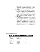
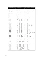
CABLE CONNECTION MATRIX
BLOOD PRESSURE CABLE
DIN Plug Pin No.
Color
Function
4 Black
Output
(+)
1 Red
Output
(-)
3 White
Exciter
(+)
5 Green
Exciter
(-)
2 Blue
ECG
ref
Temperature
(See below).
The type of cable used determines the type of probe simu-
lated, either 400 or 700 series YSI probes. Temperature is selected by a
slide switch. Prewired 400/700 YSI-series temperature cables to connect
to the temperature connector are available from Metron AS (P.N.
17443). Unterminated cables are also available.
CABLE CONNECTION MATRIX
UNIVERSAL TEMPERATURE CABLES
DIN Plug Pin No.
Color
OUTPUT 1
400 Series
OUTPUT 2
700 Series
1 Green
Tip No
conn.
2 Red
No
conn.
Tip
3 White
No
conn.
Ring
4 Black
Barrel
Barrel
NOTE
When the instrument is
switched off, all stored
information will be can-
celed.
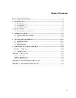
Summary of Contents for PS-416M
Page 1: ...1 1 PS 416M User Service Manual PATIENT SIMULATOR...
Page 4: ...1 4 This page intentionally left blank...
Page 6: ...1 6 This page intentionally left blank...
Page 10: ...1 10 This page intentionally left blank...
Page 12: ...2 12 This page intentionally left blank...
Page 20: ...4 20 This page intentionally left blank...
Page 28: ...5 28 This page intentionally left blank...
Page 29: ...5 29 Component Location...
Page 30: ...5 30 Schematic Diagram Part 1...
Page 31: ...5 31 Schematic Diagram Part 2...
Page 32: ...5 32 This page intentionally left blank...
Page 34: ...5 34 This page intentionally left blank...
Page 36: ...5 36...


