


5-21
5. Component Functions and Parts
This chapter provides a detailed description of the functions of the main
components of the PS-416M, as well as a parts list for cross reference. Ref-
erence is made to the component location and circuit diagrams to assist ser-
vicing personnel. These diagrams are foldouts, and located in Appendix A.
5.1 Theory of Operation
The PS-416M Patient Simulator is battery driven, and based on a Motorola
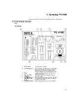
microprocessor. The unit is operated from a control panel, and generates
simulated signals for testing ECGs and patient monitors. The signals are sent
from the PS-416M via contacts situated on the front and top of the unit. The
status of the signals is then displayed on an LCD panel.
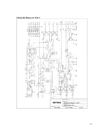
The unit is illustrated by a component location diagram and two circuit dia-
grams. The first circuit diagram 1 includes the microprocessor, operating
elements, display, power supply and circuits for simulating temperature
measurements. The second circuit diagram comprises mainly analogue am-
plifiers and circuits for generating waveforms for blood pressure and ECG.
5.2 Functions Description
1.
Power Supply
The unit is powered from either an internal 9 V battery or an external
battery eliminator. Diode D1 protects against a wrong polarization.
Power switch SW1 takes the 9V current to the power supply circuits. A
serial voltage regulator (IC5) supplies the circuits with +5V. The circuit
has an output that resets the microprocessor when the +5V supply falls
below 4.75V. A capacitive switch regulator (IC6) generates -5V from
the +5V current.
At the upper left of Circuit Diagram 1 is a DC/DC converter, which
generates
±
7V to the blood pressure output. The converter is galvani-
cally shielded from the transformer (TR1). The timer (IC7) generates a
rectangular current of approximately 30KHz, which is amplified by tran-
sistors Q1 and Q2. The primary development at TR1 is a resonance with
a multilayer capacitor (C26). The secondary AC signal is equalized by
diodes D2, D3, D7 and D8, and smoothed out by tantalum capacitors
C15 and C16. Voltage Regulator IC20 regulates the +5V power that is
used by the D/A converter on the blood pressure output.
2.
Microprocessor
The microprocessor (IC1) contains: CPU, ROM, RAM ND converter,
parallel I/O and serial I/O. Y1 functions as a clock and timer for the
processor. The frequency at pin TP1 is the crystal frequency / 4 = 2MHz.
Summary of Contents for PS-416M
Page 1: ...1 1 PS 416M User Service Manual PATIENT SIMULATOR...
Page 4: ...1 4 This page intentionally left blank...
Page 6: ...1 6 This page intentionally left blank...
Page 10: ...1 10 This page intentionally left blank...
Page 12: ...2 12 This page intentionally left blank...
Page 20: ...4 20 This page intentionally left blank...
Page 28: ...5 28 This page intentionally left blank...
Page 29: ...5 29 Component Location...
Page 30: ...5 30 Schematic Diagram Part 1...
Page 31: ...5 31 Schematic Diagram Part 2...
Page 32: ...5 32 This page intentionally left blank...
Page 34: ...5 34 This page intentionally left blank...
Page 36: ...5 36...


