Autolab/Electronic load combination
37 |
P a g e
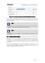
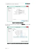
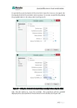
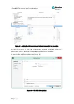
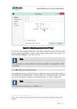
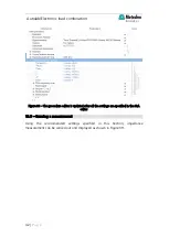
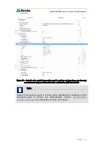
Figure 33 – Setting the parameters for the
Y input
The value of the multiplier depends on the type of electronic load and the settings
for the Kikusiu PLZ164WA in 33 A current range will be used in this section. For
this load, the multiplier is -3.3 (33 A / 10 V
).
13.1.4
– Settings for Transfer function
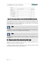
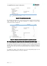
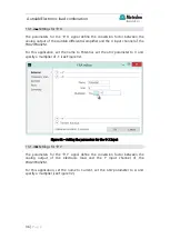
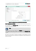
The parameters for the Transfer function define the way the transfer function is
calculated and identified during a measurement. For convenience sake, the name
and unit of the transfer function can be adjusted here, as shown in Figure 34.
2
The – sign is used to correct the output of the load for the polarity convention as indicated in
Section 5.
Note
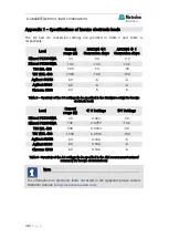
The parameters for other electronic loads are reported in the Appendix of this
document.
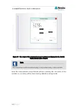
Note
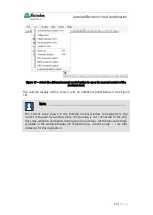
The default transfer function is identified as H.

