Autolab/Electronic load combination
10 |
P a g e
5
– Polarity convention
The NOVA software, used to control the Autolab and the electronic load
connected to it, uses the IUPAC convention for potential and current polarity.
Charging (or anodic) currents are indicated with a positive sign. Discharging (or
cathodic) currents are indicated with a negative sign.
For this application, working with an electronic load to discharge energy storage
or conversion devices, cell voltages will be positive and discharge currents will be
negative.
The software can be adjusted to account for this polarity convention.
6
– Connections to the Dynload interface
This section describes the connections required to perform the measurements with
the Autolab in combination with an electronic load. The connections depend on
the instrument type and configuration. In the rest of this document, an N series
Autolab instrument is used, however other instrumental configurations are
possible.
6.1
– Connections without a FRA module
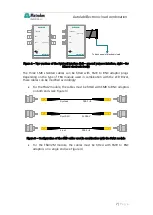
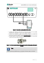
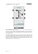
If no FRA module is present in the instrument (FRA2 or FRA32M), the connections
between the Autolab and the Dynload interface should be as described in Figure
6.
Note
The current indicated on the front panel of the electronic load will be positive.

