background image


Insert a new module for the Multi Autolab Cabinet 


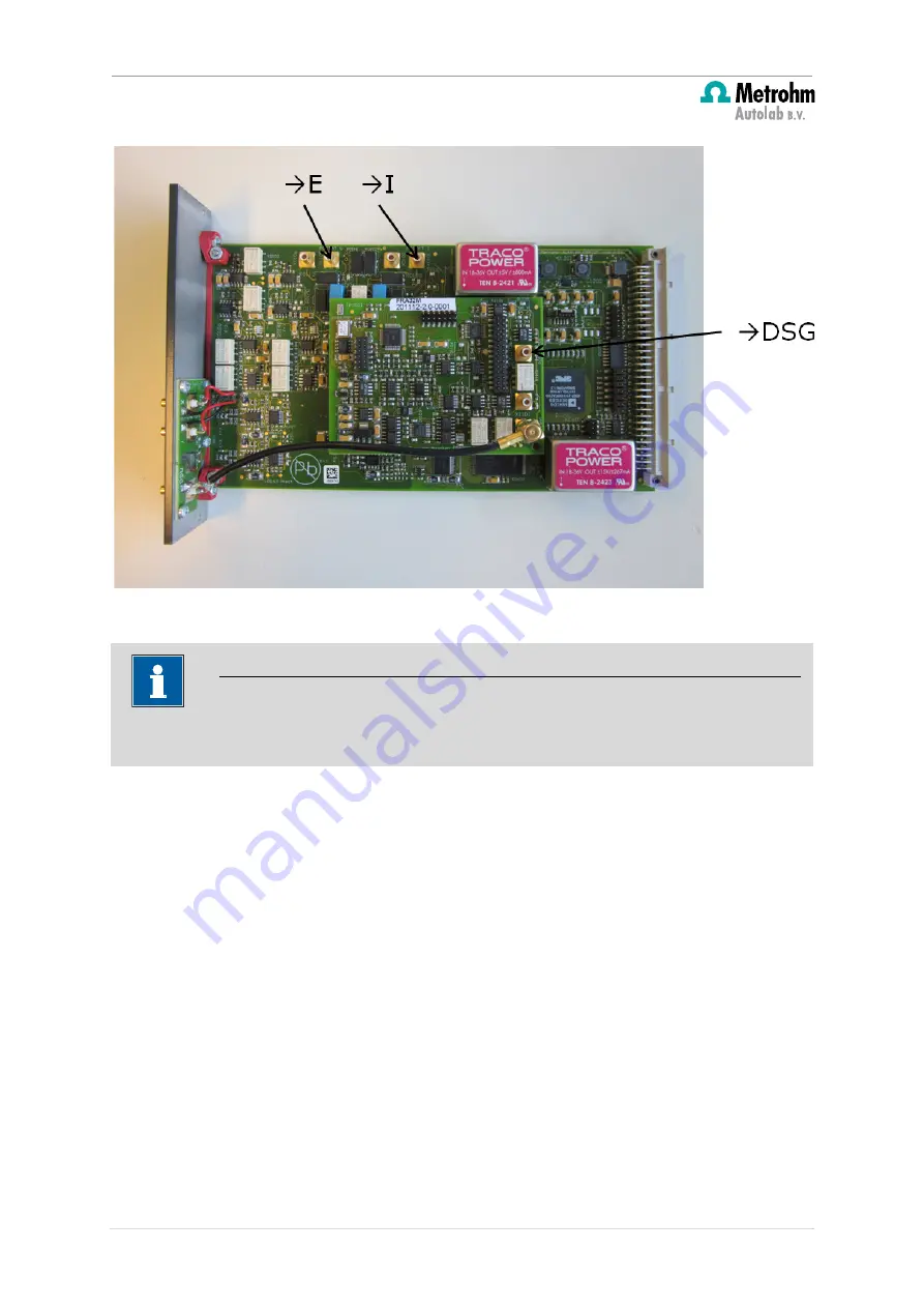
Figure 21 – Overview of the SMB connectors of the FRA32M module 


The universal white connector provided with the three analog bus connectors shown in 
Figure 18, Figure 19 and Figure 20 must be installed on the 8 pin connector located behind 
the main heat sink on the M101 or M204 module (see Figure 22).  


Note 


Connect the cable to the FRA32M module before inserting the module into the Multi 
Autolab frame. 

16 | 

P a g e


Summary of Contents for AUTOLAB MULTI M101

Page 1: ...NEW MODULE FOR THE MULTI AUTOLAB CABINET Editorial Metrohm Autolab B V Kanaalweg 29 G 3526 KM Utrecht The Netherlands Tel 31 30 2893154 Fax 31 30 2880715 E mail autolab metrohm autolab com Website ww...

Page 2: ...b M101 or M204 programming 19 5 1 The Edit Serial Number application 20 5 1 1 Installation of M101 or M204 modules into an empty Multi Autolab Cabinet 22 5 1 1 1 Create a new Multi Autolab Cabinet 22...

Page 3: ...bus cable 1 1 1 1 Nova 1 7 or higher FRA32M Module label FRA32M Analog bus cable 1 1 Nova 1 8 or higher MUX Module label MUX Digital MUX cable 1 1 Nova 1 7 or higher pX1000 Module label pX1000 Cover f...

Page 4: ...available for Multi Autolab instruments the part list for each module and the software and hardware requirements or restrictions Warning Take all the necessary steps to avoid ESD damage to the modules...

Page 5: ...he mains 2 Unscrew the four screws on the rear of the Cabinet indicated in Figure 2 Leave the screws in the top cover Figure 2 Locate the four indicated screws on the back plane of the cabinet 3 Remov...

Page 6: ...the cabinet 4 Lift the top cover and remove it from the instrument and disconnect the earth cable see Figure 4 Figure 4 Lift the cover Follow these steps to remove the front panel 1 Unscrew the four...

Page 7: ...d through holes in the bottom cover These screws must be removed without turning the Autolab upside down In order to do this slide the instrument slightly over the edge of the table and remove the fou...

Page 8: ...panel 4 How to insert the new module s The Multi Autolab Cabinets are fitted with a total of 12 module bays The module bays have alternating roles Six bays are referred to as Parent positions the six...

Page 9: ...module see Table 1 for the compatible optional modules When an optional module is installed in a daughter position it will be controlled by the M101 or M204 module installed in the parent position im...

Page 10: ...olab Cabinet Depending on the connection to the USB hub the host computer can control the following module bays main USB all the module bays in the Multi Autolab cabinet are controlled sub 1 USB modul...

Page 11: ...ing the following three M101 or M204 modules into the Multi Autolab Cabinet 3 When all the Parents positions are filled continue with the Daughter positions 4 The same alternating strategy is suggeste...

Page 12: ...sition 4 3 Installation procedure for optional modules into Multi Autolab Cabinet The Multi Autolab Cabinet can accommodate the following optional modules into a Daughter position pX1000 MUX EQCM BA F...

Page 13: ...nly be installed in a Daughter position Figure 17 CORRECT SITUATION Optional modules can only be installed in a Daughter position Note Optional modules can only be installed in the Daughter position T...

Page 14: ...ons for optional modules The following optional modules need to be connected to the parent M101 or M204 module using the provided dedicated analog bus pX1000 BA FRA32M The analog bus has a universal c...

Page 15: ...and the module specific green connector only fit the corresponding holders on the modules in one direction Additional information is therefore not required The connector for the FRA32M shown in Figur...

Page 16: ...te connector provided with the three analog bus connectors shown in Figure 18 Figure 19 and Figure 20 must be installed on the 8 pin connector located behind the main heat sink on the M101 or M204 mod...

Page 17: ...Figure 22 The analog bus connectors must be installed on the 8 pin connector located on the M101 or M204 PCB behind the main heat sink Note Install the white connector with the two notches facing towa...

Page 18: ...or M204 PCB Figure 24 shows an example of optional modules installed in Daughter positions and properly connected to the Parent M101 or M204 module through the dedicated analog bus connectors Note Dau...

Page 19: ...ule will be identified by the serial number of the cabinet and the location in the cabinet For example module MAC80002 A will indicate a M101 module located in module bay A in the Multi Autolab Cabine...

Page 20: ...M101 or M204 modules will work according to specifications however it will not be possible to identify these modules based on their positions in the Multi Autolab Cabinet 3 http www metrohm autolab c...

Page 21: ...eld can be edited the other fields are read only For the Multi Autolab instrument to work properly the following information needs to be encoded into each M101 or M204 module installed in the Multi Au...

Page 22: ...n existing Multi Autolab Cabinet need to be removed from the cabinet in order to be installed in another Multi Autolab Cabinet All three situations will be described in the following sections 5 1 1 In...

Page 23: ...hand side see Figure 27 The default serial number of the Multi Autolab Cabinet is MAC80001 for M101 or MAC90001 for M204 Click the Multi Autolab Cabinet in the list and edit the serial number of the c...

Page 24: ...s correct serial number it is possible to start adding M101 or M204 modules to this cabinet Using the drag and drop method select the AUT4XXXX or AUT5XXXX modules available in the list on the left han...

Page 25: ...lti Autolab Cabinet 1 2 The M101 or M204 module dragged into the Multi Autolab Cabinet will be listed below the MAC8XXXX or MAC9XXXX serial number see Figure 29 Note An asterisk symbol in the Edit Ser...

Page 26: ...repeated for all the M101 or M204 modules to be added to the Multi Autolab Cabinet see Figure 30 Note The listed next to each M101 or M204 module in the Multi Autolab Cabinet indicates the module posi...

Page 27: ...M101 or M204 modules are installed into an existing Multi Autolab Cabinet with at least one M101 or M204 module already installed and configured the new modules need to be added to the existing Multi...

Page 28: ...ngside the existing M101 or M204 modules installed in the Multi Autolab Cabinet 5 1 2 1 Add the M101 modules to the existing Multi Autolab Cabinet Using the procedure described in Section 5 1 1 2 drag...

Page 29: ...ting Multi Autolab Cabinet 1 2 The M101 or M204 module dragged into the Multi Autolab Cabinet will be listed below the MAC8XXXX or MAC9XXXX serial number see Figure 33 Note An asterisk symbol in the E...

Page 30: ...for all the M101 modules to be added to the existing Multi Autolab Cabinet see Figure 34 Note The listed next to each new M101 or M204 module added to the existing Multi Autolab Cabinet indicates the...

Page 31: ...Assign the position number for each M101 or M204 module Requirement Connect the M101 or M204 cell cable to each M101 or M204 module in the Multi Autolab Cabinet before continuing Short circuit the RE...

Page 32: ...r M204 modules added to the Multi Autolab Cabinet When the M101 or M204 module is selected the cell will be switched on with the internal dummy cell active The status LED located on the front panel of...

Page 33: ...e easily identified see Figure 37 Figure 37 The cell status LED of the selected M101 or M204 module position 1 is lit green Write the identified position number in the frame on the right hand side of...

Page 34: ...round brackets X 5 1 4 Save the changes When all the M101 or M204 modules installed in the Multi Autolab Cabinet have been assigned a correct and unique position the changes can be permanently saved...

Page 35: ...information to the on board EEPROM The information specified for each module will be saved in the on board EEPROM of each M101 or M204 module Once the information has been successfully uploaded the sy...

Page 36: ...be tested To verify that the modules are correctly identified close the Edit Serial Number application switch the Multi Autolab Cabinet off start the NOVA software and switch the Multi Autolab Cabinet...

Page 37: ...nd position in the new instrument The module can be simply removed from the old cabinet and installed into the new cabinet The Edit Serial Number displays the configuration for the connected Multi Aut...

Page 38: ...43 The Multi Autolab Cabinet configurations are displayed in the frame on the left hand side Click the M101 or M204 module coming from the original cabinet and using the drag and drop method move it t...

Page 39: ...or M204 module from one cabinet to another 1 2 After moving the M101 or M204 module from the original cabinet to the new cabinet it will be displayed as being part of the new cabinet configuration wit...

Page 40: ...on of the module the following tests should be performed to verify that the module is working as expected 1 Connect mains power 2 Switch Autolab on 3 Install the delivered software Nova 1 7 or later f...

Reviews: