background image


Functional Description 

IV - 26 

Function/Arbitrary Waveform Generators 


Functional Description (contd.) 

To Set the Delay 


1.  Press Pulse 

 Delay, to set the delay.  

The delay shown on the screen when the instrument is powered is the 
default value or the set value beforehand. When changing the function, if 
the current value is valid for the new waveform, it will be used 
sequentially.  


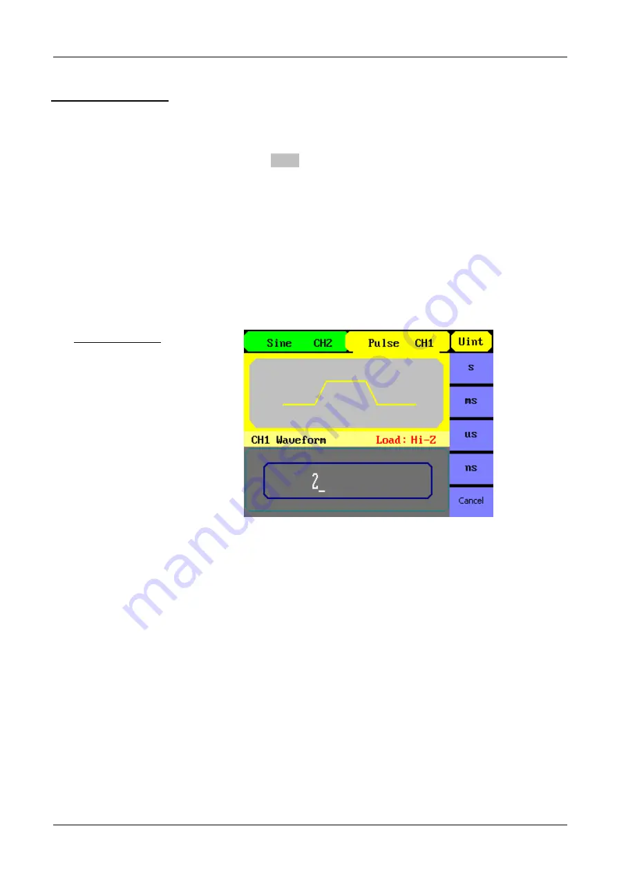
2.  Input the desired delay 

Use the keypad or the knob to input the desired value, choose the unit, 
and press the corresponding button. The generator will change the 
waveform immediately. 


Setting the Delay 


Summary of Contents for GX 1025

Page 1: ...5 5 5 5 5 5 5 5 5 5 5 5 5 5 5 5 5 5 5 5 5 5 5 50 0 0 0 0 0 0 0 0 0 0 0 M M M M M M M M M M M MH H H H H H H H H H H Hz z z z z z z z z z z z G G G G G G G G G G G GX X X X X X X X X X X X 1 1 1 1 1 1...

Page 2: ...mp signals 20 3 To set Square signals 22 4 To set Pulse signals 24 5 To set Noise signals 27 6 To set arbitrary signals 28 7 To generate the modulated Waveform 35 8 To generate Sweep 41 9 To generate...

Page 3: ...Refer to the operating manual to find out the nature of the potential hazards and the action necessary to avoid such hazards Application or withdrawal not authorized for non insulated conductors carry...

Page 4: ...n of the equipment to the manufacturer the shipping charge from the customer to the manufacturer is at the customer s expense The guarantee does not apply in the following conditions inappropriate use...

Page 5: ...ns meet the SCPI specification requirements From the characteristics and specifications given below you will understand how this generator can satisfy your requirements DDS technology provides precise...

Page 6: ...itrary Waveform Generators Description of the instrument contd Front panel Rear panel The external input voltage can t be over 12 Vpp otherwise instrument gets damaged Modulation In Ext Trig Gate Fsk...

Page 7: ...escription of the instrument contd Handle Adjustment To adjust the handle position of the Function Arbitrary Waveform Generator please grip the handle by the sides and pull it outward Then make the ha...

Page 8: ...n Arbitrary Waveform Generators Description of the instrument contd Display Interface Sine Wave is the default display signal Waveform Display Window Parameter Display and Editing Window Operation Men...

Page 9: ...ith the waveform selection settings Step 1 Press Sine and the waveform window will display sine waveform The generator can generate sine signal with a frequency from 1 Hz to 25 MHz GX 1025 or 50 MHz G...

Page 10: ...ncy from 1 Hz to 25MHz and variable duty cycle A shown the default signal parameters are 1 kHz frequency 4 0 Vpp amplitude 0 Vdc offset and 50 duty cycle Step 3 Press Ramp button and the waveform wind...

Page 11: ...gnal with a frequency from 500 Hz to 5 MHz and variable pulse width and delay As shown the default signal parameters are 1 kHz frequency 4 0 Vpp amplitude 0 Vdc offset 200 s pulse width Step 5 Press N...

Page 12: ...veform contd Step 6 Press Arb button and the waveform window displays arbitrary waveform The generator can generate repeatable arbitrary waveform signals with at most 16 K points and 5 MHz frequency A...

Page 13: ...dulated waveforms will be generated The modulated waveform can be changed by modifying the parameters such as type internal external modulation depth frequency waveform etc The generator can modulate...

Page 14: ...ast for certain times of waveform cycle N Cycle Burst or be controlled by external gated signals Gated Burst Burst applies to all kinds of waveforms but noise can only be used in gated burst Generally...

Page 15: ...used to directly set the parameters value 3 Knob is used to change a signal digit value whose range is 0 9 Clockwise to increase 1 5 To Use Store Utility Function Those three buttons on the operation...

Page 16: ...select Freq Cursor is located in the frequency parameter area in the parameter display window and users can set the frequency value here Sine parameters display interface Menu Explanations of Sine wav...

Page 17: ...you want to set the period for the waveform press Freq Period button again to switch to the period parameter The current operation is displayed in inverse color 2 Input the desired frequency Use the k...

Page 18: ...hen changing the function if the current value is valid for the new waveform it will be used sequentially If you want to set the waveform by high level or low level press the Ampl HLevel or Offset LLe...

Page 19: ...et shown on the screen when the instrument is powered is the default value or the set value beforehand When changing the function if the current value is valid for the new waveform it will be used seq...

Page 20: ...rameter Display Interface Menu Explanations of Square Waveform Function Menu Explanation Freq Period Set the signal frequency or period The current parameter will switch at a second press Ampl HLevel...

Page 21: ...when the instrument is powered is the default value or the set value beforehand When changing the function if the current value is valid for the new waveform it will be used sequentially 2 Input the d...

Page 22: ...e parameter display window and users can set the symmetry value here Ramp Parameter Display Interface Function Menu Explanation Freq Period Set the signal frequency or period The current parameter wil...

Page 23: ...when the instrument is powered is the default value or the set value beforehand When changing the function if the current value is valid for the new waveform it will be used sequentially 2 Input the d...

Page 24: ...Interface Function Menu Explanation Freq Period Set the signal frequency or period The current parameter will switch at a second press Ampl HLevel Set the signal amplitude or high level The current pa...

Page 25: ...n when the instrument is powered is the default value or the set value beforehand When changing the function if the current value is valid for the new waveform it will be used sequentially 2 Input the...

Page 26: ...n the instrument is powered is the default value or the set value beforehand When changing the function if the current value is valid for the new waveform it will be used sequentially 2 Input the desi...

Page 27: ...tion menu The parameters for noise waveforms are amplitude high level and offset low level As is shown below in the soft key menu select Offset Cursor is located in the Offset parameter area in the pa...

Page 28: ...are frequency period amplitude high level and offset low level and phase Arb Parameter Display Interface Menu Explanations of Arb Waveform 1 2 Function Menu Explanation Freq Period Set the signal fre...

Page 29: ...ere are forty eight built in Arbitrary Waveforms and user definable Arbitrary Waveforms inside the Generator To select one of them follow the instructions below Press Arb Load Wform to enter the inter...

Page 30: ...waveform Choice Validate the built in waveform Common Built In Arbitrary Waveform interface Menu Explanations of Common Built In Arbitrary Waveform Function Menu Explanation StairUp Select the built i...

Page 31: ...logarithmic rise waveform Sqrt Select the built in square root waveform Root3 Select the built in Root3 waveform X 2 Select the built in X 2 waveform X 3 Select the built in X 3 waveform Sinc Select t...

Page 32: ...of Project Built in Arbitrary Waveform Function Menu Explanation Cardiac Select the built in electrocardiogram ECG signal waveform Quake Select the built in loma prieta earthquake waveform Chirp Sele...

Page 33: ...ect the built in Blackman windows waveform Gaussian Select the built in Gaussian window waveform Triangle Select the built in triangle window waveform Hairs Select the built in hairs window waveform B...

Page 34: ...ctional Description contd b To Select the Stored Waveform Press Arb Load Wform Stored Wforms and enter the following interface As is shown below use the direction keys or knob to choose the correspond...

Page 35: ...ers can set the source internal external frequency deviation modulating waveform and carrier waveform In ASK users can set the source internal external modulating waveform and carrier waveform In FSK...

Page 36: ...ype AM amplitude modulation Shape Sine Square Triangle UpRamp DnRamp Noise Arb Choose the modulating waveform To change the carrier waveform parameter press Sine Square etc Internal The source is inte...

Page 37: ...frequency deviation Type FM Frequency modulation Shape Sine Square Triangle UpRamp DnRamp Noise Arb Choose the modulating waveform To change the carrier waveform parame ter press Sine Square etc Inte...

Page 38: ...dulating signal keeping frequency and phase constant Setting Interface of ASK Waveform Parameter Press Mod Type ASK to enter the following menu Function Menu Settings Explanation Key Freq Set the freq...

Page 39: ...ncy generator or the signal voltage level offered by the Ext Trig Gate Fsk Burst connector in the rear panel Setting Interface of FSK Waveform Parameter Press Mod Type FSK to enter the following inter...

Page 40: ...ter the following interface Function Menu Settings Explanation PM Freq Set the modulating waveform frequency Frequency range 2mHz 20kHz internal source only Phase Dev Set the phase deviation between t...

Page 41: ...his button to enter the following menu Set the waveform parameters by using the operation menu Function Menu Settings Explanation Swp Time Set the time span of the sweep in which the frequency changes...

Page 42: ...q or center freq and freq span to set the range of the frequency Press the button again to switch between each other Function Menu Settings Explanation Trig Out Open Off Set signal triggered at rise e...

Page 43: ...s button to enter the following interface Set the waveform parameters by using the operation menu Setting Interface of Burst Waveform Parameter Set the N Cycle Burst Press Burst N Cycle to enter the f...

Page 44: ...at Rise Edge Signal Triggered at Fall Edge Turn off Trigger Setting Cycles Infinite Set the number of the bursts in a N Cycle Set the number of the bursts in a N Cycle to be infinite Delay Set the de...

Page 45: ...rbitrary waveform file All kinds of files Browser Path Directory File Shift between the path Directory and file Save Save the waveform to the appointed place Recall Recall the waveform or setting info...

Page 46: ...utton enter the desired name Press Save to finish To Save Data Users are allowed to store data document in any of the 10 non volatile memories If the place is already occupied new document will cover...

Page 47: ...DG1000 Use the right key to open the lower directory and up and down key to select the file Workspace Input the file name and save 3 Remove the Mobile Disk Remove the Mobile Disk from the interface Th...

Page 48: ...to save a file named NEWFILE follow the steps 1 Press Input Type En to enter the English interface 2 Input the file name NEWFILE Use the Knob to adjust the cursor s horizontal position and the up and...

Page 49: ...Inverse The System Setting provides the setting for Language Display Beep Screen Guard Format Power System Configure and default setting Test provides the self testing and calibration function Press...

Page 50: ...Offset Set the DC voltage level To Shift into the Arbitrary Waveform Output 1 Press Utility DC DC Off to close DC output and return to arbitrary waveform output 2 Press any functional button and the...

Page 51: ...For the Output Connector on the Front panel the Generator has a built in 50 series impendence If the actual load does not match the set one the displayed amplitude and offset will be incorrect This fu...

Page 52: ...level low In the Inverse Mode the Waveform that corresponds to the Sync Signal does not inverse The Sync Signal is a Pulse Signal with fixed positive pulse width which is more than 50ns For non modula...

Page 53: ...ettings Explanation Mode DC AC Set the coupling mode to DC Set the coupling mode to AC Default Set count settings to default HFR On Off Open the high frequency rejection filter Close the high frequenc...

Page 54: ...ny button the resume ScrnSvr Off Deactivate the screen saver program Clock Internal External Choose the system clock source Power On Choose the configuration setting when the machine is powered Two ch...

Page 55: ...d 1 Set the Format Press Utility System Number Format to enter the following interface Set the number Format Function Menu Settings Explanation Point Using dot to represent point Using comma to repres...

Page 56: ...can have various forms 1 as point press Separator On the example is as followed 2 as point press Separator On the example is as followed 3 as point press Separator Off the example is as followed 4 as...

Page 57: ...are as followed Factory Default Setting Output Default Function Sine Wave Frequency 1kHz Amplitude Offset 4Vpp 0Vdc Phase 0 Terminals High Z Modulation Default Carrier 1kHz Sine Wave Modulating 100Hz...

Page 58: ...ss Utility Test Cal to enter the following menu Test Cal function Menu Menu Explanations of Test Setting Function Menu Explain Self Test Perform system self test Menu Explanations of Self Test Functio...

Page 59: ...d test interface the on screen lathy rectangle shapes represent the front panel keys The shapes with two arrows beside them represent the front panel knobs Test all keys and knobs and you should also...

Page 60: ...arrows beside them represent the front panel knobs The clew words Press 7 Key to continue Press 8 Key to exit is displayed You could press the 7 button continuously for testing when buttons are light...

Page 61: ...aining the file ADSs into the USB connector on the front panel of the generator 2 Press the UTIL button to access the UTILITY menu 3 Select the button next page 2 2 4 Press the select Update menu 5 Se...

Page 62: ...oard and choose the unit kHz The frequency is set to be 50 kHz Set the amplitude 1 Press Ampl to choose Ampl which will display in white color 2 Input 5 from the keyboard and choose the unit Vpp The a...

Page 63: ...he amplitude 1 Press Ampl to choose Ampl which will display in white color 2 Input 2 from the keyboard and choose the unit Vpp The amplitude is set to be 2 Vpp Set the offset 1 Press Offset to choose...

Page 64: ...rom the keyboard and choose the unit mVpp The amplitude is set to be 100mVpp Set the offset 1 Press Offset to choose Offset which will display in white color 2 Input 20 from the keyboard and choose th...

Page 65: ...from the keyboard and choose the unit V The high level is set to be 5V Set the low level 1 Press Offset and choose the LLevel which will display in white color 2 Input 1 from the keyboard and choose t...

Page 66: ...ss Noise Ampl and choose the Ampl which will display in white color 2 Input 50 from the keyboard and choose the unit mVpp The amplitude is set to be 50 mVpp Set the Offset 1 Press Offset to choose Off...

Page 67: ...nu Set the frequency 1 Press Freq and choose Frequency which will display in white color 2 Input 5 from the keyboard and choose the unit MHz The frequency is set to be 5MHz Set the amplitude 1 Press A...

Page 68: ...kHz 2 Press Ampl to choose Ampl which will display in white color Input 5 from the keyboard and choose the unit Vpp to set the amplitude 5 Vpp 3 Press Offset to choose Offset which will display in wh...

Page 69: ...ut 1 from the keyboard and choose the unit Vpp to set the amplitude 1Vpp 3 Press Offset to choose Offset which will display in white color Input 0 from the keyboard and choose the unit Vdc to set the...

Page 70: ...hoose Ampl which will display in white color Input 1 from the keyboard and choose the unit Vpp to set the amplitude 1Vpp 4 Press Offset and choose Offset which will display in white color Input 0 from...

Page 71: ...d choose Ampl which will display in white color Input 1 from the keyboard and choose the unit Vpp to set the amplitude 1Vpp 4 Press Offset and choose Offset which will display in white color Input 0 f...

Page 72: ...oose Ampl which will display in white color Input 5 from the keyboard and choose the unit Vpp to set the amplitude 5Vpp 4 Press Offset and choose Offset which will display in white color Input 0 from...

Page 73: ...0KHz 3 Press Ampl and choose Ampl which will display in white color Input 5 from the keyboard and choose the unit Vpp to set the amplitude 5Vpp 4 Press Offset and choose Offset which will display in w...

Page 74: ...it kHz to set the frequency 5KHz 3 Press Ampl and choose Ampl which will display in white color Input 5 from the keyboard and choose the unit Vpp to set the amplitude 5Vpp 4 Press Offset and choose Of...

Page 75: ...MHz Output channels 2 Sample rate 125 MSa s Arbitrary waveform length 16 kpts Frequency resolution 1 Hz vertical resolution 14 bits Waveform Sine Square Triangular Pulse Gaussian Noise 48 types of arb...

Page 76: ...50 MHz 3 dB Arbitrary waveform 1 Hz 5 MHz 1 Hz 5 MHz Resolution 1 Hz Accuracy within 1 year 100 ppm Temperature coefficient 5 ppm C Sine Wave Spectrum Purity Harmonic Distortion CH1 CH2 1 Vpp 1 Vpp 1...

Page 77: ...typical value 1 kHz 1 Vpp Triangle Ramp Wave Linearity Peak value output 0 1 typical value 1 kHz 1 Vpp symmetric 100 Symmetry 0 to 100 Pulse Wave Specification Pulse width max 2000s min 20 ns min reso...

Page 78: ...50 Ohm 4 mVpp 6 Vpp high impedance Vertical accuracy 5 1 mVpp of setting value 0 1 dB for f 100 kHz 0 15 dB for 100 kHz f 5 MHz Amplitude flatness compared to 100 kHz sine waveform 5 Vpp 0 3 dB for f...

Page 79: ...uare Ramp Triangle Gaussian Noise Arbitrary 2 mHz 20 kHz Frequency deviation GX 1025 0 12 5 MHz GX 1050 0 25 MHz PM Modulation CH1 CH2 Carrier Sine Square Triangle Arbitrary except DC Source Internal...

Page 80: ...lation amplitude 6 6 V corresponding modulation depth 0 100 Sweep CH1 CH2 Carrier Sine Square Ramp Triangle Arbitrary except DC Type linear logarithmic Direction Up down Sweep time 1 ms 500 s 0 1 Trig...

Page 81: ...e instrument gets damaged Trigger Input Voltage level input TTL compatible Slope Up or down optional Pulse width 100 ns Input impedance 10 k DC coupling Response time Sweep 500 s typical value Burst 5...

Page 82: ...o 1 Hz 200 MHz 200 mVpp 5 Vpp DC deviation range 1 5 VDC 100 mHz 100 MHz 20 mVrms 5 VAC DC DC coupling 100 MHz 200 MHz 40 mVrms 5 VAC DC 1 Hz 100 MHz 50 mVpp 5 Vpp Manual AC coupling 100 MHz 200 MHz 1...

Page 83: ...ltage 100 240 VACRMS 45 440 Hz CATII Consumption 30 W Fuse 1 A 250 V Environment Operation 0 C 40 C Temperature Storage 20 C 60 C Cooling method natural cooling down below 35 C 90 relative humidity Te...

Page 84: ...Support http www chauvinarnoux com SUNSUPPORT SUPPORT page pageSupportLog asp Power cord that fits the standard of destination country USB cable accessories Cable mains EURO 1 5m elbowed AG0416 Cable...

Reviews: