background image

23 


Send Units 

Specifies whether or not the unit type for a given value is sent along with the 
value. Set to Yes or No using the appropriate softkey. 

Send Eol(End of Line) 

Configures the desired character to be sent at the end of an output line. 
CR(Carriage Return), Line Feed(LF) or CR &LF can be selected using the 
appropriate softkey. EOL can also be set to None.  

Field Delimiter 

Configures the desired field delimiter(separator) to Comma or Tab. Set to 
desired delimiter using the appropriate softkey.  


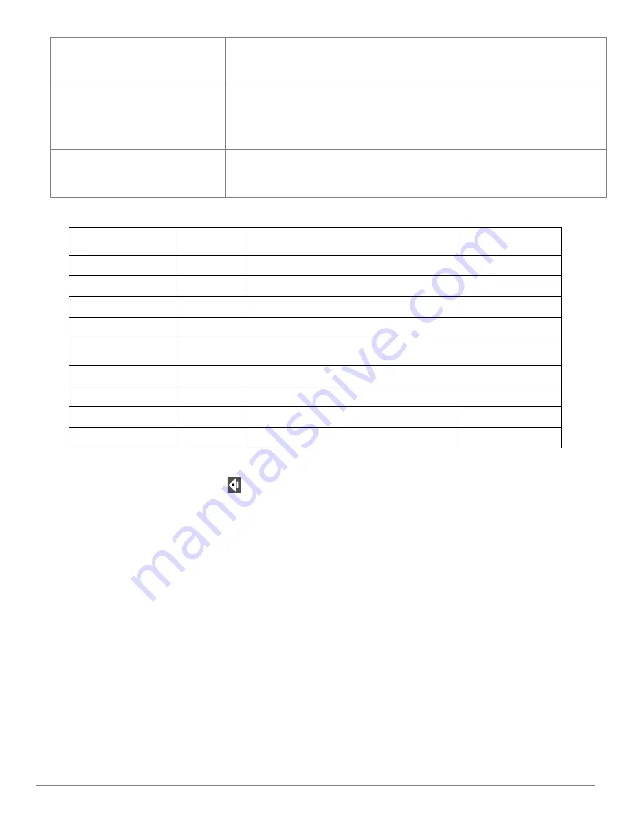
MLX200 9 Pin 

Dsub(F) 

Description  Switch Device(Footswitch/Buttons/ETC) 

RS232 9 Pin 

Dsub(M) 

1  TRIG_2_IN  SW2 Common 

NC 

2  RX_IN 


3  TX_OUT 


4  TRIG_1_OUT   

NC 

5  GND 

SW1 & SW2 (Normally Open) & Earth 

Ground 

6  TRIG_1_IN  SW1 Common 

NC 

7  TRIG_3_IN   

NC 

8  TRIG_2_OUT   

NC 

9  TRIG_3_OUT   

NC 


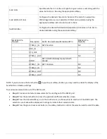
NOTE: If you do not see the Send button(      )in your top or softkey toolbar, you may need to enable the display of the 
Send button in Desktop settings. 

To send measurement data out of the RS232 port. 


Step 1:

 Produce some feature measurements for sending out of the RS232 port.


Step 2:

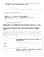
 Press the Send button to access the position/coefficient selection screen.


Step 3: 

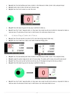
Press the desired softkey, or use the touch screen, to choose what to send out of the RS232 port. The 

selections you make will be displayed in orange to indicate their selection state.


Step 4: 

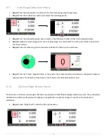
Press the green check-mark button in the sofkey toolbar to confirm the selection and transmit the data.


Summary of Contents for Mx200

Page 1: ...Mx200 User s Guide MetLogix Inc 175 Canal Street Manchester NH 03101 USA Tel 603 836 4452 Fax 603 369 6499 info metlogix com www metlogix com ...

Page 2: ...ansmitted in any form or by any means electronic mechanical photocopying recording or otherwise without prior written permission of Metlogix Inc Requests to Metlogix Inc for permission should be addressed to the Customer Services Department Metlogix Incorporated 175 Canal Street Manchester New Hampshire 03101 Limit of liability and disclaimer of warranty While this guide was prepared with great ca...

Page 3: ...or touchscreen or through the use of softkeys and function keys on the rubberized keypad Features are measured by entering points manually using a simple crosshair probe or automatically using optical edge detection The probes include Simple crosshair Used for manual point entry Optical edge detection Identifies the location of a point as the optical crosshair probe crosses an edge There are two m...

Page 4: ...n Setup About page in the Mx200 software Information describing the system hardware A detailed description of the problem and the steps that you ve already attempted to resolve it User Guide Contents This user guide is divided into 8 sections The User Interface Probing constructing and creating features How to establish datums Zeroing Tolerancing Programming Data View Optical Edge Detection Option...

Page 5: ...ata View screen Other screens will be described as part of instructions detailed later in this guide Screen contents include The main screen function in the center The Feature List on the left The System toolbar at the top The Measure toolbar at the bottom 2 2 Touch Screen Or not The Mx 200 features a color touchscreen that can be used to interact with the device For caustic or harsh operating env...

Page 6: ...gs screen Arrow Keys Navigate the settings menu screens The left and right arrows go in a level or out a level The up and down arrows move the current selection up down Power Key Single Press to Power On When On Single Press for Screen Off Long Press for Power Off Soft Keys 1 6 Executes the softkey button commands selection displayed above the key DRO Keys Execute X Y Z Q zerroing funciton Select ...

Page 7: ...p setting for a particular function is set to Bottom or Both it will be displayed in the Mx200 s Extra Functions menu This menu can be displayed by pressing the Menu key once Additional keypresses of the Menu button will cycle through the pages of the Extra Functions menu Function Button Icon Description Program Button The Program Button navigates to the part program view Data View Button The Data...

Page 8: ...gnification softkey menu and also shows the currently selected mag Send Button The Send button initiates the RS232 send function Ref Frame Button The Ref Frame button toggles the Abs Inc datum frame DMS DD Button The DMS DD button toggles between Degrees Minutes Seconds and Decimal Degrees mode Setup Button The Setup button navigates to the Mx200 setup screen ...

Page 9: ...or cross hair The second button is the Create Feature function allowing you to create a feature in space addressed later in the guide The third icon displays the feature type you have selected to measure The fourth is the repeat measure function allowing repeat measurements of the same feature And lastly the construction mode function which allows you to construct a feature relationship from previ...

Page 10: ...pes can be applied by pressing the Change Type key For circles features other fit types include Max Inscribed Fit What is the largest pin that could fit in the this hole Min Superscibed Fit What is the largest diameter created from the three outer most points ISO Fit Best Form Fits the feature to the best or lowest form 3 3 Creating Features On occasion you may need to create a feature somewhere i...

Page 11: ...e below uses 5 parent circels The bolt hole circle construction will be displayed in black Pro Tip You can always use the keypad up down arrows or the touchscreen to move up and down the feature list viewing the detailed results information for the selected feature Other Feature Constructions To perform other construction types first declare the feature type you want as a result of the constructio...

Page 12: ...e position Step 1 Move the stage to the desired measurement reference position Step 2 Press the Home button to display the DRO view if necessary Step 3 Press the DRO Zeroing Button screen or keypad to zero the stage position for the desired axes 4 2 Presetting the Stage Position to Specific Coordinates To preset a stage position Step 1 Move the stage to the desired measurement reference position S...

Page 13: ...list and Feature Detail screen 4 Zero the line angle by pressing the Angle button to align the part to the X axis The X and Y coordinate button images will change from X and Y to X and Y to indicate that a skew alignment exists The Angle value label will turn blue and a will be added to indicate it is a datum feature 4 4 Constructing a Skew Alignment Between 2 Circles A skew alignment line can als...

Page 14: ...use in future measurements 4 5 Part Datums One or two datums can be used as measurement references Datum 1 and Datum 2 can be used interchangeably at the user s discretion A part datum can be established by Zeroing a feature location Or Presetting a feature location Datum features can be probed constructed from parent features or created from data provided by the user It is assumed in the followin...

Page 15: ...hted in orange Step 5 Use the keypad to enter the desired reference coordinate values The Cancel key can be used to delete any incorrectly entered values Step 6 Press the Return arrow to display the Home screen The preset datum coordinates will be displayed 4 8 Using Two Datums To establish two zero points first follow the steps outlined above to set an initial part datum XY origin Step 1 Now crea...

Page 16: ... last digit of a nominal value using the touch screen moving your finger left and right will index the value up and down until the desired value is reached Step 7 Once your nominals are specified press the TOL key then press the Add Tolerance Button You can now select the tolerance types you would like to add In the example below a cartesian tolerance for X and Y have been added as well as a size ...

Page 17: ...pes are applied in a similar method as described above In some cases however tolerances can make use of a reference feature other than the datum The two most common examples of this are for Concentricity and Angularity tolerances An example has been provided below Use the following steps to apply a concentricity tolerance to a circle IMPORTANT In all cases where a reference feature will be used fo...

Page 18: ...r your tolerance highlight the Reference Feature field located under the Tol column and use the numeric keypad to enter the feature number of the desired reference feature In the example below you can see that feature number 4 has been referenced ...

Page 19: ...the Menu button Step 2 Press the New Part button This will clear all features and datums from the system Step 3 Press the Program button then the New Program button Enter a number to be assigned to the program and press Enter You will see a small red dot in the upper right toolbar indicating you are in Record mode Step 4 Measure the bottom line of the part and Zero the y axis Step 5 Measure the le...

Page 20: ...ne construction for example you can create a program for that sequence set the Macro flag to Yes and then assign it to one f the numeric keypad buttons In Setup scroll down to Quick Keys press Enter Highlight Number pad and press Enter scroll down to the keypad number you want to assign the macro to A dialog will be displayed requesting the program number you want to assign to the key Enter the nu...

Page 21: ...splayed in one of three views CSV Standard and Tolerance Each has a different layout for measurement data select the one that best suits your needs You can Print Export or Send RS232 your data from the Mx200 to a printer USB storage device or external data collection system 7 1 Printing report data Before printing you must first configure the printer to be used Once set up is complete pressing the...

Page 22: ... to be properly configured and the correct cable needs to be used in order to successfully send the data The RS232 settings screen contains setup parameters for configuring the general purpose IO port for on the Mx200 readout for serial data output The port parameters configured on the Mx200 should match that of the connected device PC Note The general purpose IO port on the Mx200 is used for both...

Page 23: ...n NC 2 RX_IN 2 3 TX_OUT 3 4 TRIG_1_OUT NC 5 GND SW1 SW2 Normally Open Earth Ground 5 6 TRIG_1_IN SW1 Common NC 7 TRIG_3_IN NC 8 TRIG_2_OUT NC 9 TRIG_3_OUT NC NOTE If you do not see the Send button in your top or softkey toolbar you may need to enable the display of the Send button in Desktop settings To send measurement data out of the RS232 port Step 1 Produce some feature measurements for sendin...

Page 24: ...n 8 2 Simple Crosshair Probe The simple crosshair probe is used to measure a single point at a time by manually lining up the crosshair center with a location on the feature edge and then pressing the Point Counter button or the keypad Enter button The DRO current stage position is continually updated while probing with the Simple Crosshair 8 3 Manual Edge Detection Probe The Manual Edge detection...

Page 25: ...er of points required for each feature type is shown in the table below Probing more than the minimum number of required points increases measurement accuracy Feature Type Minimum Number of Points Points One Lines Two Circles Three Distances Two only Angles Two on each leg Skew Two Datum One 8 6 Using the Probes The procedure for using the three probe types is simple and is identical for all featu...

Page 26: ...p 1 Press the Home button to return to the main measuring view if necessary Step 2 Press the Probe Menu button and select the Manual Edge probe Step 3 Press the desired Measure Feature button in the Measure toolbar circle in the example below Step 4 Sweep the optical edge sensor over a feature edge The probe will fire and a tone will be produced Step 5 Press the point counter button to confirm ent...

Page 27: ...rement Step 6 Probe the remaining points necessary to define the feature in the same way Step 7 Press the Finish keypad button or the green check mark touchscreen button to complete the feature measurement The feature will be shown in the Feature list and Feature Detail screen 8 10 Optical Edge Sensor Teach Probe Teach is the basic optical edge calibration required by the Mx200 optical edge detect...

Page 28: ...sture driven control of start and stop measure commands and by automatically determining and entering the feature type for line and circle features Note It may be necessary to enable the Edge Logic function in the Mx200 setup menus To enable EdgeLogic navigate to the Mx200 Settings then access the setup screen called Optical Edge and set the enable flag for EdgeLogic to Yes To use the Edge Logic f...

Page 29: ...ne features These line features should span a major axis of the measuring system Step 2 Press the Measure Circle button and select the two lines from the feature list and then press Enter Step 3 A prompt will be displayed where the diameter of the gage ball can be entered Enter the desired Gage Diameter and press Enter The newly constructed Gage Circle will be added to the feature list 9 3 Gage Li...

Page 30: ...ould like to assign the keypad number to Step 5 Press the Ok softkey to confirm the selection Note The Number Pad Quick Key loading of part programs will only be permitted while in the main DRO view This is to prevent undesired calling of a program while using other Mx200 screen While in the main DRO view press the number pad key associated with your program it will be loaded and run Footswitch Us...

Reviews: