background image

TWRF1 SCR Power Controller 


Description 

Rev 2 

Ametek HDR Power Systems 

CHAPTER 1 - Description 


1.1 

General Description 

The  TWRF1  is  a  Single-phase,  phase-fired  power  controller,  and  can  operate  with  a  wide  variety  of 
input signals and line voltages up to 575 Vac and currents ranging from 30 through 225 amperes.  The 
TWRF1’s  output  voltage  is  proportional  to  its  input  signal,  with  the  output  voltage  regulated  to  +1% 
with a +10% line voltage change.  The TWRF1 features pulse-train firing which provides high immunity 
to  possible  SCR  firing  disturbances,  and  phase-lock  loop  circuitry  which  ensures  line  frequency 
synchronization.    Other  features  are  input  isolation  from  ground,  soft-start,  and  automatic  restart 
circuitry.    A  customer  provided  potentiometer  controls  to  the  Command  signal.  A  variety  of  other 
external control methods are available,  more detailed description of the features mentioned above is 
provided in Chapter 3 of this manual. 
 

1.2 

Application 

Phase-Fired  SCR  Power  Controllers  provide  infinitely  variable  firing  angles  for  precise  control  of 
single-phase  power  to  resistive  or  inductive  loads.  This  precise  control  is  essential  for  transformer 
coupled  loads  or  loads  with  great  resistance  changes  due  to  temperature  or  start-up.  Phase-Fired 
units  may  also  be  used  on  straight  resistive  loads  as  well,  but  the  lower  power  factor  and  higher 
harmonics may present a problem to other equipment mounted nearby. A zero fired model would be a 
better choice. 
 

1.3 

Operation 

The  TWRF1  accomplishes  power  control  by  the  switching  action  of  a  pair  of  inverse-parallel  power 
SCRs. The switching, or gating, of the SCRs is controlled by a digital firing control circuit synchronized 
“in phase” with line frequency (either 50 or 60 Hz).  A soft-start (approximately a 1 cycle ramp) feature 
is standard that allows the Power Controller to fire into the primary of a transformer or to control power 
to heating elements which have a large resistance change during start-up. The output may be adjusted 
by the on-board multi-turn potentiometers or by a voltage or current signal from a process controller. 
ZERO and SPAN controls allow the user to calibrate the SCR unit's output to the process command 
signal. Terminals are available for connection of a remote manual potentiometer. 
 
An overcurrent trip is included.  This circuit protects from output current overloads by serving as a fast-
gate shutdown (similar to an electronic fuse.)  Trip point is adjustable from 30% to 200% of the SCR 
Power Control’s current transformer rating.  When the peak current level exceeds the preset trip level, 
SCRs  are  gated  off,  and  the  load  current  is  shut  down  within  1/2  cycle.    A  form  C  relay  output  is 
provided. 


The overcurrent trip includes a Form C relay output and provisions for a remote overcurrent reset push 
button.  The relay output terminals for the TWRF1 are 35 and 36 for the N.C. and 36 and 37 for the 
N.O. The remote reset PB connects to terminals 33 and 34.   Reference Figure 3.7. 
 

1.4 

Selecting the Proper Rated Power Controller 

Use the Table below to select the proper sized TWRF1.  You will need the incoming line voltage and 
the transformer  leakage impedance.  For voltages other than 480V, ratio the  incoming voltage  using 
the 480V chart provided below.  For example, a 240V system the kVA would be half that on the chart 
for any given kVA.  The kVA is based upon the one cycle surge ratings of the SCRs installed in each 
of the power controls. 


Summary of Contents for TWRF1 SCR Series

Page 1: ...tion and Maintenance Manual Number 9100051 Revision 2 530 Lakeview Plaza Blvd Ste C Worthington Ohio USA 43085 Toll Free 1 888 PWR CNTL 797 2685 Phone 614 308 5500 Fax 614 308 5506 Web www hdrpower co...

Page 2: ...presentative nearest you please call Ametek HDR Power Systems main office at 614 308 5500 Revision 1 December 2017 Initial Release Revision 2 Aug 2022 General Revision 2022 by Ametek HDR Power Systems...

Page 3: ...mote Manual Control with a Potentiometer 11 3 4 Process Command Input Control 12 3 5 Auto Manual Control with a Controller and Remote Potentiometer 13 3 6 On Off Control 14 3 7 Shutdown 14 3 8 Overcur...

Page 4: ...wer Controller ii Ametek HDR Power Systems Rev 2 7 1 Warranty 24 7 2 In house Repair Services 24 7 3 Field Service Repairs 25 APPENDIX 26 Appendix A System Schematic 26 Appendix B 30 60 A Outline 27 A...

Page 5: ...ut Connections 13 Figure 3 4 Auto Man Control with Controller and Remote Potentiometer 13 Figure 3 5 On Off Control 14 Figure 3 6 Shutdown Control 14 Figure 3 7 Current Limit Trip Board 15 Figure 4 1...

Page 6: ...Table of Contents TWRF1 SCR Power Controller iv Ametek HDR Power Systems Rev 2...

Page 7: ...anch circuit fused disconnect or circuit breaker with this Power Controller is required to ensure the safety of operating personnel CAUTION HAZARDOUS VOLTAGES exist at the Power Controller Load AT ALL...

Page 8: ...Safety Instructions TWRF1 SCR Power Controller 2 Ametek HDR Power Systems Rev 2...

Page 9: ...the SCRs is controlled by a digital firing control circuit synchronized in phase with line frequency either 50 or 60 Hz A soft start approximately a 1 cycle ramp feature is standard that allows the Po...

Page 10: ...ch the output can increase to prevent high inrush currents with transformer coupled loads or high cold to hot resistance ratios such as tungsten heating elements The rate of increase is limited to app...

Page 11: ...red Power output linearity versus control signals input 2 Non isolated 5 Isolated Power SCRs protection Current surge Subcycle I T semiconductor fuse OPTIONAL Transient voltage spikes dv dt Metal Oxid...

Page 12: ...Description TWRF1 SCR Power Controller 6 Ametek HDR Power Systems Rev 2...

Page 13: ...15 30 A and 10 AWG or larger wire for the other sizes NOTICE Use copper conductors rated 75 C minimum for all model current ratings On the internal side of the TWRF1 the wire from L2 should connect to...

Page 14: ...nal Input HDR s TWRF Phase Fired SCR Power Controllers are configured for a potentiometer non isolated but has the capability of having either an isolated current or non isolated voltage Command Signa...

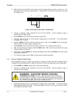
Page 15: ...cedure as follows 1 Open the SCR power controller and locate transformer T1 The primary side of T1 transformer will contain two wires one black the other white and black Refer to figure 2 3 Figure 2 3...

Page 16: ...Operation TWRF1 SCR Power Controller 10 Ametek HDR Power Systems Rev 2...

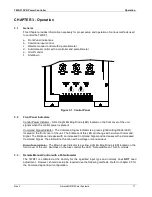
Page 17: ...icator The Command Signal Indicator is a green Light Emitting Diode LED located on the front cover of the unit The brilliance of this LED will change with a current Command Signal The brilliance incre...

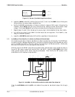
Page 18: ...ge reading is at maximum h If necessary readjust ZERO with remote potentiometer fully CCW and SPAN control and remote potentiometer fully CW i Turn off the line power to the TWRF1 and disconnect the t...

Page 19: ...eter CW until the output trips to the desired level 3 5 Auto Manual Control with a Controller and Remote Potentiometer On closed loop processes it may be desirable to be able to operate the unit manua...

Page 20: ...enable the TWRF1 Figure 3 5 On Off Control Calibrate the system by performing the steps in 3 3 Note that zero power demand is accomplished by opening the contacts with the controller and maximum powe...

Page 21: ...Adjust the OC CUR PWR potentiometer fully CW b With the power controller at full output adjust OC CUR PWR potentiometer CCW until the unit shuts off c Adjust the OC CUR PWR potentiometer slightly CW d...

Page 22: ...Operation TWRF1 SCR Power Controller 16 Ametek HDR Power Systems Rev 2...

Page 23: ...ing of the SCRs is controlled by a digital firing control circuit synchronized to the line frequency 50 or 60 Hz The firing control circuit may be manually controlled by the built in ZERO control or a...

Page 24: ...rnal control device From midpoint to extreme CW is the positive control region whose extremes correspond to 0 and 100 power output respectively as manually adjusted The SPAN control is used as a final...

Page 25: ...riable from zero to some intermediate value but cannot be brought to maximum The symptoms listed may be caused by one or more of the following an environmental problem faulty input power or load conne...

Page 26: ...ns should be free of dust or dirt for proper heat transfer and free of obstructions which could prevent proper airflow Contamination The unit should be periodically cleaned of all dust and dirt Howeve...

Page 27: ...n the Rx1 scale the resistance should be infinite in both directions If a shorted component is indicated in any of these cases replace it 2b Firing control section defective Replace the fuse and retur...

Page 28: ...rrange for service at your site or by shipment to Ametek HDR Power System as you request We will make every possible attempt to support your emergency on site needs regardless of how contacted 6 2 Spa...

Page 29: ...0 2087000 2099112 6791114 1 1 1 1 60 Ampere Units PCB Assy PF1 Extended Gate PCB Assy Over current Trip PCB Assy DVDT SCR dual pkg 1622 A 1400 V 2099160 2087000 2099112 6722114 1 1 1 1 90 Ampere Units...

Page 30: ...Y OR OTHERWISE IN NO EVENT WILL AMETEK HDR BE LIABLE FOR INCIDENT OR CONSEQUENTIAL DAMAGES NOR IN ANY EVENT SHALL HDR S LIABILITY EXCEED THE UNIT PRICE OF ANY DEFECTIVE PRODUCT OR PART 7 2 In house Re...

Page 31: ...Power Systems 25 7 3 Field Service Repairs Repairs may be performed at your location Please contact Ametek HDR Power Systems at 614 308 5500 to discuss terms and conditions to get the current service...

Page 32: ...Warranty TWRF1 SCR Power Controller 26 Ametek HDR Power Systems Rev 2 APPENDIX Appendix A System Schematic Note Thermostat and fan not included on 60 A and smaller models...

Page 33: ...TWRF1 SCR Power Controller Appendix Rev 2 Ametek HDR Power Systems 27 Appendix B 30 60 A Outline R...

Page 34: ...Warranty TWRF1 SCR Power Controller 28 Ametek HDR Power Systems Rev 2 Appendix C 90 225 A Outline R...

Page 35: ...Notes...

Page 36: ...530 Lakeview Plaza Blvd Ste C Worthington Ohio 43085 USA...

Reviews: