TWRF1 SCR Power Controller
Operation
Rev 2
Ametek HDR Power Systems
11
CHAPTER 3 - Operation
3.1
General
This Chapter provides information necessary for proper setup and operation of various methods used
to control the TWRF1.
a. Front Panel indications
b. Command input control
c. Remote manual control with a potentiometer
d. Auto/manual control with a controller and potentiometer
e. On/off control
f. Shutdown
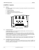
Figure 3.1 Control Panel
3.2
Front Panel Indicators
Control Power Indicator – A Red Light Emitting Diode (LED) located on the front cover of the unit
signals when the control power is present.
Command Signal Indicator - The Command Signal Indicator is a green Light Emitting Diode (LED)
located on the front cover of the unit. The brilliance of this LED will change with a current Command
Signal. The brilliance increases with an increased Command Signal and decreases with a decreased
Command Signal. The LED will not function with a voltage or manual input.
Blown Fuse Indicator - The Blown Fuse Indicator is a yellow Light Emitting Diode (LED) located on the
front cover of the unit. Switches on the fuse controls the LED. Not available on 15-40 A models
3.3
Remote Manual Control with a Potentiometer
The TWRF1 is calibrated at the Factory for the specified input type and normally does
NOT
need
adjustment. However, should a setup be required use the following methods. Refer to chapter 2.5 for
the Command signal input configuration.
Summary of Contents for TWRF1 SCR Series
Page 6: ...Table of Contents TWRF1 SCR Power Controller iv Ametek HDR Power Systems Rev 2...
Page 8: ...Safety Instructions TWRF1 SCR Power Controller 2 Ametek HDR Power Systems Rev 2...
Page 12: ...Description TWRF1 SCR Power Controller 6 Ametek HDR Power Systems Rev 2...
Page 16: ...Operation TWRF1 SCR Power Controller 10 Ametek HDR Power Systems Rev 2...
Page 22: ...Operation TWRF1 SCR Power Controller 16 Ametek HDR Power Systems Rev 2...
Page 35: ...Notes...
Page 36: ...530 Lakeview Plaza Blvd Ste C Worthington Ohio 43085 USA...


