


20
A01-00055 Rev M
• If your system is compatible with “simulated relay contact” or
designed for active high/iow 12VDC signals, use the DB9 Port
on UPM back panel. This port provides access to basic-signal
interfaces for use with some industrial control systems or with
legacy and open source UPM monitoring software to trigger
automated computer shutdown on low battery conditions.
The table below is a pin map to the various signals available on the
DB9 port.
DB-9 Definition for UPM
Pin
Description
1
Low Batt - RS232 Level
2
RS232 RX
3
RS232 TX
4
Inverter Shutdown during AC Fail
5
Ground
6
AC Fail - RS232 Level
7
AC Fail - Simulated NO Contact (programmable)
8
Low Batt - Simulated NO Contact (programmable)
9
Simulated Contact Ground
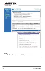
REMOTE MONITORING AND ALARM NOTIFICATIONS VIA IT
NETWORK OR BUILDING MANAGEMENT SYSTEMS
SCENARIO A:
Monitor UPM Health and Power Quality via existing
SNMP monitoring system.
• Purchase the optional ManageUPS Net adapter (SNMP/WEB card,
PN: AM-P1-R2), install it in the Extended Communications Slot of
the UPM and connect it to the TCP/IP LAN that the computers are
connected to.
Configure the embedded email client in the adapter to access
an SMTP server on your enterprise network and send alarm
notifications to email recipients.
Information & User Guide for ManageUPS Net Adapter can be found at
this link: http://connectivity.powervar.com/products/manageups/


