Metcalfe CJ24 Operating & Maintenance Instructions Download Page 13

13 


SECTION 3 - PREPARING THE MACHINE FOR OPERATION 


3.1  Unpacking the machine 

 
The machine is packed in a strong carton box.  Open this box from the upper side, as indicated 
by  the  arrow,  remove  the  anti-impact  materials  and  raise  the  machine,  holding  it  with  both 
hands  at  the  bottom.    Free  the  machine  from  the  protective  nylon  wrapping  and  perform 
preliminary cleaning of the external surface of the machine, using a soft dry cloth. 
 

3.2  Setting up for operation 

 
Transfer the machine to the place where it is required for operation, bearing in mind its size and 
the  dimensions  of  the  containers  for  the  products  to  be  processed  and  for  finished  products, 
leaving a sufficient space all around the machine for movement. 
The base must rest on a solid, uniform and properly levelled surface. The machine requires no 
anchoring to the supporting surface. 
 

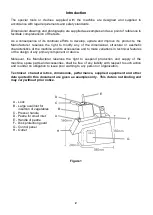
3.3  Installing dismantled parts 

 
To facilitate packing and transportation, certain components of the machine are supplied 
dismantled.  However, tests are carried out at the factory before shipment to verify that they 
function correctly when installed.  To install these components, proceed as follows: 

  Take hold of the presser lever and pull upwards (C Fig.1) 

  Rotate the knob (A Fig.1) by a half- turn until a click is heard and the released knob itself 

partially moves out. 

  With both hands take hold of and raise the cover (F Fig.1) 

  On the rotating hub, install first of all an expulsion disc (high-ridge or low-ridge according to 

requirements refer to table 2), making sure that the drive pins on the hub are properly 
inserted in the holes in the disc. 


NOTE: The expulsion disc MUST ALWAYS BE INSTALLED so that the discs can operate 
in the correct position. 

 
If you have to carry out operations that require only one disc, insert only one rotating disc above 
the expulsion disc. If you have to carry out operations that require the simultaneous use of two 
discs (Table 1), insert the following devices in the order given below: 
 
1° - Expulsion disc (high-ridge or low-ridge) 
2° - Fixed grid 
3° - Rotating disc 
 

FOR  OPTIMUM  USE  OF  ALL  TYPES  OF  ROTATING  DISCS  AND,  IF  REQUIRED, 
SIMULTANEOUS  USE  OF  DISCS  WITH  FIXED  GRIDS  REFER  TO  TABLE  1,  WHERE  ALL 
POSSIBLE FUNCTIONAL COMBINATIONS ARE INDICATED. 


3.4  Connections 

 
Sections  1.1  and  2.1  describe  the  fundamental  operations  for  installation  and  the  values  of 
absorbed  power.    Connection  of  the  machine  to  the  mains  circuit  must  be  carried  out  by  a 
specialised  installation  operator,  who  must  have  all  the  technical  instruments  required  for  this 
purpose. 

Summary of Contents for CJ24

Page 1: ...1 METCALFE CJ24 VEGETABLE PREPARATION MACHINE Operating Maintenance Instructions...

Page 2: ...e variations in technical features or the design of any primary component or device Moreover the Manufacturer reserves the right to suspend production and supply of the machine spare parts and accesso...

Page 3: ...operator and risk prevention SECTION 3 PREPARING THE MACHINE FOR OPERATION 3 1 Unpacking the machine 3 2 Setting up for operation 3 3 Installing dismantled parts 3 4 Connections SECTION 4 USING THE MA...

Page 4: ...0 75HP 1 0A Net weight 20 kg Average noise level 58 dB A Overall dimensions length depth height 23 5 cm x 51 cm x 48 5 cm Dimensions of packing length depth height 32 cm x 60 cm x 55 cm Overall weigh...

Page 5: ...5 Table 1...

Page 6: ...2 5 H 4 H 6 H 8 H 10 No No No No No Low Low Low Low Low Strips 6 x 6mm 8 x 8mm 10 x 10mm E 6 E 8 E 10 B 6 B 8 B 10 Low Low Low Cubes 8 x 8 x 8mm 10 x 10 x 10mm 12 x 12 x 12mm 20 x 20 x 20mm E 8 E 10 E...

Page 7: ...7 Slicing discs Slicing discs Stick cutting discs Stick cutting discs E2 E3 E4 E5 E6 E8 E10 E14 S1 S2 E1 X1 8 Slicing disc with an adjustable thickness from 1 to 8 mm All stainless steel H4 H6 H8 H10...

Page 8: ...d correctly and if the presser C Fig 1 is not lowered completely These devices are of the active safety type with forced opening of contacts IEC 337 1A and are used to protect the operator s hands so...

Page 9: ...his opening does not allow the hands or fingers to reach the moving parts inside the machine The safety measures and devices mentioned above conform to prescribed standards in European regulations EEC...

Page 10: ...seriously damage the machine itself whatever product is being processed inside it and also the operator or other persons 8 Before starting work button up tightly and securely the cuffs of your overal...

Page 11: ...pt to remove the plug from the socket by pulling on the power cable Protect the cable against high temperature contact with oil and sharp edges 20 The machine must not be used in the open without adeq...

Page 12: ...a qualified civil or industrial installation technician with specific experience or recognized specialist respecting all current technical and safety regulations of the country where the machine is us...

Page 13: ...he presser lever and pull upwards C Fig 1 Rotate the knob A Fig 1 by a half turn until a click is heard and the released knob itself partially moves out With both hands take hold of and raise the cove...

Page 14: ...ttached with the sequence indicated on the plate attached to the cable The exact combination of the cyclical sequence of phases of the machine with that of the mains circuit ensures the correct direct...

Page 15: ...slices when cutting vegetables of an almost cylindrical shape such as carrots cucumbers courgettes etc feed the vegetables into the small circular inlet and then use the presser pestle device D Fig 1...

Page 16: ...tton again on the machine If the machine still does not run a maintenance technician must be consulted The technician will have to test the above devices again and check the condition of the fuse used...

Page 17: ...with the new value 240 After completing the connections run a test and check for correct direction of rotation of the motor Figure 4 Parts List See diagram on next page Part Number Description Part Nu...

Page 18: ...18 CJ24 Breakdown Drawing Exploded view of the machine and replaceable parts...

Page 19: ...the factory properly packed and labelled All repairs alterations or replacement of materials or parts not authorised by Metcalfe will automatically void all warranties in their entirety There is a lim...

Page 20: ...V M Insulation 500V M Load KVA Load KVA Leakage MA Leakage MA Polarity leads only Polarity leads only Electrical PAT Certificate Test Detail Results Test Detail Results Item Item Class Class 1 Class 2...

Reviews: