


54
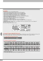
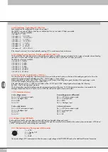
3.3.4.2 Signal range - Signal_RangeAI_x_I5F50_Sxx
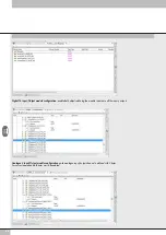
Each channel can be configured with a type of input signal.
The 0x8050 is an array of 8 bytes. Each input is defined by 4 bits, up to a total of 2 bytes per module.
The following types are available:
• Init value = 0 OFF
• Init value = 1 0..10 VDC
• Init value = 2 - 10/+10 VDC
• Init value = 3 0…5 VDC
• Init value = 4 -5 / +5 VDC
• Init value = 5 1…5 VDC
• Init value = 6 0…20 mA
• Init value = 7 4…20 mA
• Init value = 8 -20 / + 20 mA
If the channel is not used, it must be disabled by selecting OFF in order to avoid any interference
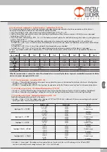
3.3.4.3 Filtering the value measuredo - FilterMeasuredValueAI_x_I5F51_Sxx
This function filters the value measured to make reading more stable. A mobile average is calculated on the number of samples chosen. Reading
slows down as the number of values increases. Each input is defined by 4 bits, up to a total of 2 bytes per module.
The following values are available:
• Init value = 0 No filter
• Init value = 1 2 values
• Init value = 2 4 values
• Init value = 3 8 values
• Init value = 4 16 values
• Init value = 5 32 values
• Init value = 6 64 values
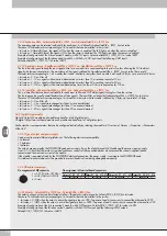
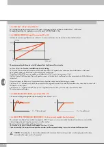
3.3.4.4 User full scale - UserFullScaleAI_x_I5F52_Sxx
This value can be set to change the scale of numerical values sent to the control system as a function of the analogue signal value. It must be
enabled by setting AnalogueInputDataFormat_I5F01_S04 Init value = 1 Linear scaled.
Makes it possible to set values up to 32767. The value set is valid for positive and negative signals, therefore if the signal range is set to
0-10 VDC for example, the maximum value will be 32767.
If the signal range is set to +/-10VDC the limit values will be +32767 and -32768. Setting higher values displays the following:
Bus Error - Error in Configuration Parameters.
This function makes it possible to obtain a read-out in engineering format, therefore if a 0-10 bar pressure transducer is connected to the
analogue channel and the user full scale is set to 10000, the value of the signal is expressed in mbar.
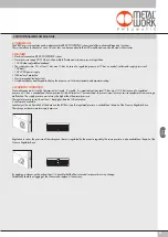
3.3.5 Analogue 4-Output M8 Module
Each module can handle up to 4 analogue outputs with freely configurable voltage and current.
This module converts signals with a resolution of 15 bits plus the sign. The numerical values settable in the control system are between –32768 and
+32767. Some parameters can be configured individually.
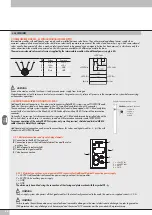
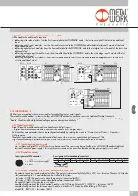
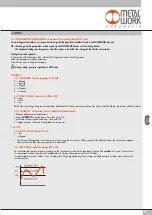
3.3.5.1 Electrical connections: Pin assignment of M8 connector
The supply vVDC corresponds to either the power supply voltage of the POWERLINK node or the Additional Electrical Connection.
1 = +VDC
2 = + Analog OUT
3 = GND
4 = Shield
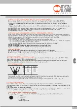
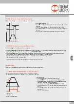
3.3.4.5 Connection of sensors
3-wire voltage sensors
Pin 1 = +VDC sensor power supply
Pin 2 = + Analogue input
Pin 3 = GND
Pin 4 = NC
4-wire voltage sensors (differential)
Pin 1 = +VDC sensor power supply
Pin 2 = + Analogue input
Pin 3 = GND
Pin 4 = - Analogue input
2-wire current sensors
Pin 1 = +VDC sensor power supply
Pin 2 = + Analogue input
Pin 3 = NC
Pin 4 = NC
3-wire current sensors
Pin 1 = +VDC sensor power supply
Pin 2 = + Analogue input
Pin 3 = GND
Pin 4 = NC
Summary of Contents for EB 80 ETHERNET POWERLINK
Page 1: ...MANUALE D USO USER MANUAL ...