


50
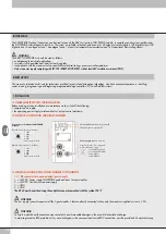
3. ACCESSORIES
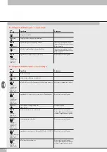
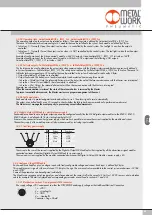
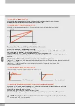
3.1 INTERMEDIATE MODULE - M, WITH ADDITIONAL POWER SUPPLY
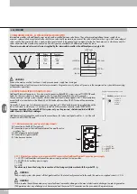
Intermediate modules with additional power supply can be installed between valve bases. They either provide additional power supply when
numerous solenoid pilots are activated at the same time or electrically separate some areas of the valve island from others, e.g. when some solenoid
valves need to be powered off when a machine safety guard needs to be opened or an emergency button has been pressed, in which case only the
valves downstream the module are powered on. Various types are available with different pneumatic functions.
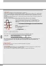
The maximum solenoid valve control current supplied by the intermediate module with additional power supply is 8A.
WARNING
It cannot be used as a safety function as it only prevents power supply from turning on.
Manual operation or faults can cause involuntary movements. For greater security, relieve all pressure in the compressed air system before carrying
out hazardous operations.
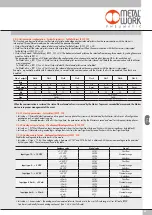
PIN
Colour
Function
1
Brown
+VDC
2
White
+VDC
3
Blue
GND
4
Black
GND
+VDC Valve
+VDC Bus
Bus Line
+VDC Valve
+VDC Bus
Bus Line
+VDC Valve
3.2 ADDITIONAL ELECTRICAL CONNECTION - E0AD
Additional Electrical Connection – E can be used to connect multiple EB 80 systems to one POWERLINK node.
To do this, the main island must be equipped with a C3-type blind end plate with an M8 connector.
The connection of multiple systems requires all the additional islands to be equipped with C3 blind end plates,
except for the last one that must be fitted with a C2 blind end plate with an EB 80 Net serial line termination
connector.
Optionally, if a provision for subsequent upscale is required, a C3 blind end plate can be installed also on the
last-in-line island, in which case it is necessary to add an M8 termination connector code 02282R5000.
For proper operation of the entire EB 80 Net system, only use the prewired, shielded and twisted M8-M8
cables shown in Metal Work catalogue.
Additional electrical connection can be used to connect bases for valves and signal modules - S, just like with
islands with a POWERLINK node.
WARNING
Failure to make the earth connection may cause faults and irrevocable damages in the event of electrostatic discharge. In order to guarantee
IP65 protection class, any discharge must be conveyed and the unused M12 connector must be provided with a protective cap.
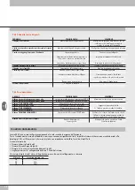
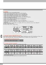
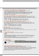
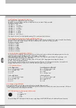
3.2.1.1 Electrical connections: pin assignment of M8 connector for Additional Electrical Connection power supply
1 = 24VDC Additional electrical connection power supply and input/output modules
2 = 24VDC Valve auxiliary power supply
3 = GND
4 = GND
The device must be earthed using the connection of the closing end plate marked with the symbol PE
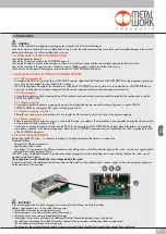
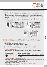
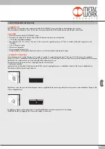
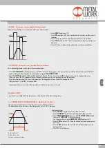
3.2.1 Electrical connections and signal display elements
A
Connection to the EB 80 Net network
B
Connection to power the Additional electrical line and the valve
auxiliary line
C
EB 80 diagnostic indicator light
D
Connection to Signal modules
E
Valve base connection
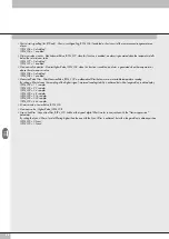
1 = +24VDC bus
2 = +24VDC valve
3 = GND
4 = GND
WARNING
The bus supply system also powers all the Signal modules S that are directly connected to the node; the maximum supplied current is 3.5 A.
End plate with intermediate control
EB 80 Net
(M8 Female Connector)
1 = CAN H
2 = CAN L
3 = Token
4 = GND
Summary of Contents for EB 80 ETHERNET POWERLINK
Page 1: ...MANUALE D USO USER MANUAL ...