2
MONTAGGIO E COLLAUDO PNEUMATICO
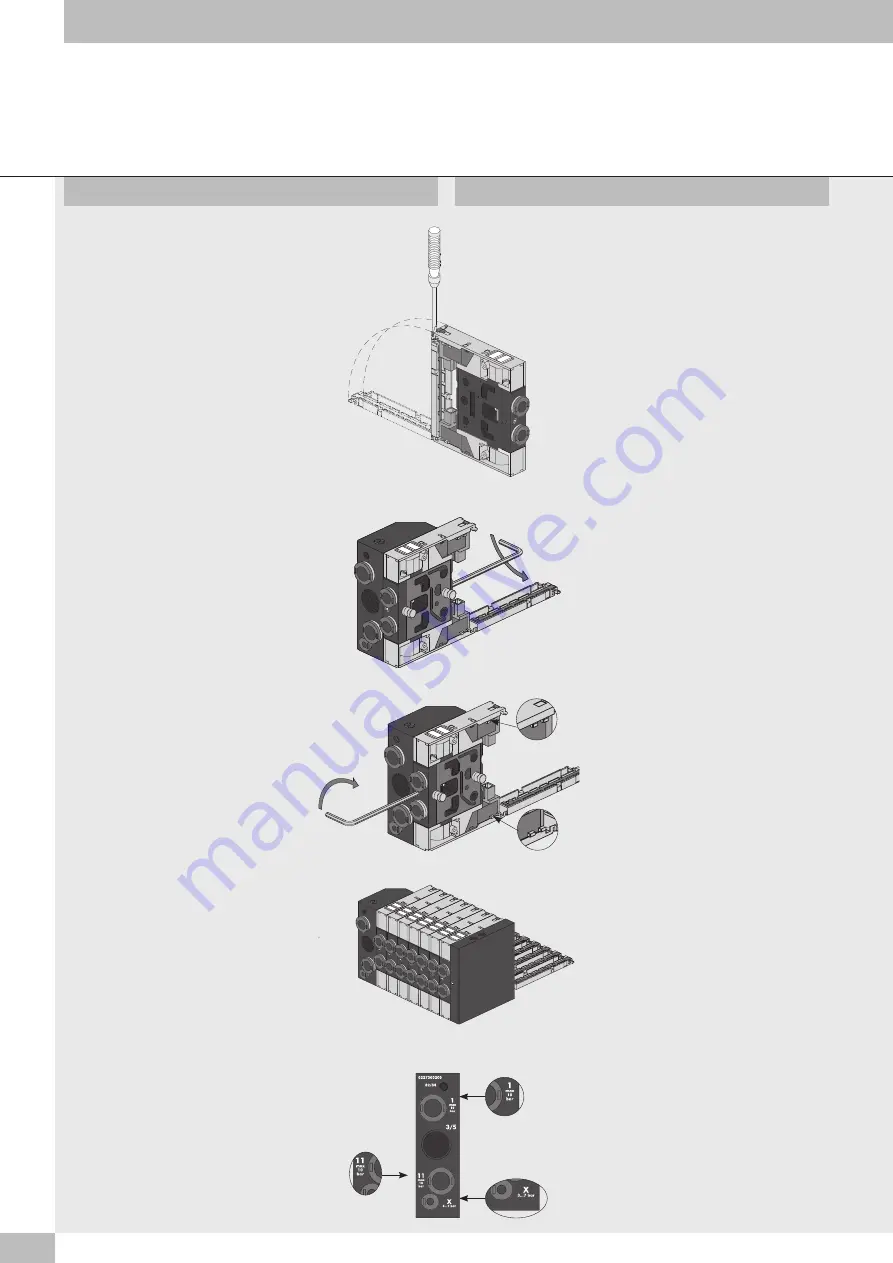
Aprire lo sportello posteriore della valvola,
mediante cacciavite o con le dita, per avere
accesso al sistema di bloccaggio.
Inserire la valvola sul terminale di ingresso.
Open the rear door to the valve with a
screwdriver, or your fingers, to access the
blocking system.
Insert the valve on the input terminal.
ASSEMBLY AND PNEUMATIC TESTING
Serrare il grano di bloccaggio posteriore
con chiave esagonale CH2 con coppia di
serraggio di 2 Nm.
Tighten the rear locking grub screw with Allen
key CH2 to a torque of 2 Nm.
Serrare il grano di bloccaggio anteriore
con chiave esagonale CH2 con coppia di
serraggio di 2 Nm
Tighten the front locking grub screw with Allen
key CH2 to a torque of 2 Nm.
Proseguire con la stessa modalità al montaggio
delle altre valvole fino al terminale cieco,
avendo cura di controllare che i dentini A di
ogni piastrina si incastrino nella successiva e
anche nell’apposita sede del terminale cieco.
Continue in the same way to assemble the
other valves as far as the blind terminal.
Make sure that the small teeth “A” of each
plate engage with the successive ones and
also with the relevant seat in blind terminal.
Dopo il montaggio è necessario effettuare il
collaudo pneumatico dell’isola controllando le
tenute generali. Tappare le bocche di uscita
delle valvole e collegare all’alimentazione le
bocche del terminale di ingresso contrassegnate
dai numeri identificativi 1, 11, X. La pressione
da utilizzare per il collaudo deve essere
compresa tra i due valori limite indicati
sul terminale di ingresso vicino ad ogni
connessione.
After fitting it is necessary to perform the
pneumatic test on the island to check general
tightness. Plug the valve output fittings and
connect the terminal input fittings marked with
identification numbers 1, 11, X to the supply.
The pressure used for the test must always be
between the two limit values indicated on the
terminal input close to each connection.
A
A


