


31
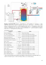
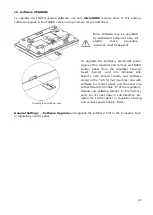
Wiring diagram of control of the switching valve in
the reserve boiler, where: 1 – ecoMAX regulator,
2 – reserve boiler, 3 – relay, 5 – switching valve
servo (with limit switches). Note: terminals
22,21,24 have to be galvanically insulated from
terminals 12,11,14.
13.14
Connection of alarm signalling
Regulator may announce alarm conditions by
activating an external device (e.g. a bell or
GSM device to send a text message).
Alarm signalling may be deactivated by
setting the H-output function to alarms.
Service Settings
→
H-output
→
H-output
function
Connection of an external alarm annunciator. 1-
regulator , 2 – external alarm annunciator, 3 –
relay
.
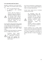
13.15
Connection of mixer
When connecting mixer servo,
take due care to prevent boiler
overheating, which may occur
when the flow of boiler water is
limited. You are advised to get
familiar with the position of the
valve
corresponding
to
its
maximum
opening
before
commencement of work so that
you may ensure heat collection
from the boiler at any time it is
required by opening it completely.
The regulator works only with mixing valve
servos equipped with limit switches. Use of
other servos is not allowed. The servos of full
turn time from 30 to 255 s may be used.
Description of mixer connection:
Description of mixer connection:
- connect mixer temperature sensor, -
connect mixer pump wiring,
- switch on the regulator and select proper
mixer support
in the service menu
Service settings
Mixer 1 Settings
- enter the proper
Valve Opening Time
in
Service Settings (this time should be
indicated on servo rating plate e.g. 120 s).
- connect power supply to the regulator and
switch on the regulator to start the mixer
pump,
- determine direction of servo closing/
opening. For this purpose, set the selector
Summary of Contents for ecoMAX860P2-T
Page 2: ...2...
Page 6: ......
Page 7: ...REGULATOR INSTRUCTION MANUAL ecoMAX860P2 T...
Page 19: ...19 CONTROLLER INSTALLATION AND SERVICE SETTINGS MANUAL ecoMAX860P2 T...
Page 43: ......
Page 44: ......
Page 45: ......
Page 46: ......
Page 47: ......


