


MC³ 24.96.EX O&M Manual
Page 28
08/14/01 4:34 PM/LDD
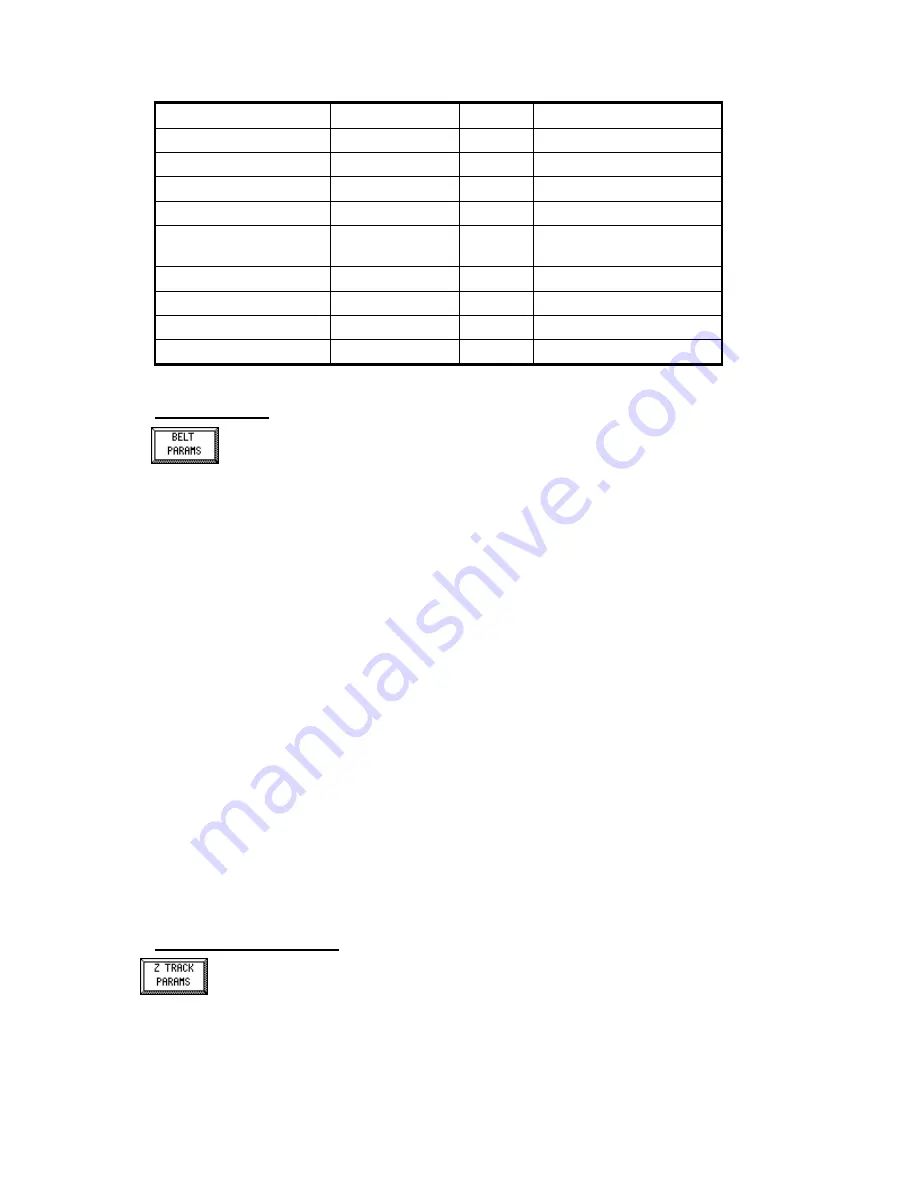
Parameter
Default
Min
Max
High Delay
10 seconds
0
3600 seconds (1 hour)
Low Delay
10 seconds
0
3600 seconds (1 hour)
Startup Delay
0 seconds
0
3600 seconds (1 hour)
Overload Limit
Design Load
1
150% of Design Load
Underload Limit
- 10% of Design
Load
- Design
Load
Design Load
High Speed
Design Speed
0
150% of Design Speed
Low Speed
0
0
Design Speed
High Speed Delay
10 seconds
0
3600 seconds (1 hour)
Low Speed Delay
10 seconds
0
3600 seconds (1 hour)
Belt Parameters
To enter numeric values for the Belt parameters, touch the Belt Parameter button from
the first Setup Screen menu. The display will be a Numeric Entry Screen. Use the
directions on page 9 to change the value of the parameter.
Pulses / Rev
The Pulses/Belt Rev variable represents the number of pulses from Tacho #1 for one revolution of
the feeder’s belt. Limits are minimum of 1 and maximum of 1,000,000. This value is normally set
by the using the Speed Calibration procedure, see page 49.
Length
The belt length variable represents the belt length in the currently selected units (feet or meter).
Limits are minimum of 1 and maximum of 50,000.
# Proc Revs
The “Number of Calibration Procedure Revolutions” variable represents the number of belt
revolutions to perform for calibration procedures with the exception of the Speed Calibration.
Limits are minimum of 1 and maximum of 100.
# Speed Revs
This parameter is used to determine the number of revolutions to use for the Speed Calibration
(page 49). Limits are minimum of 1 and maximum of 100.
Nominal Speed
This is the speed of the belt when no tacho is used on the belt pulleys and the belt will run at a
constant speed. This is normally used for a belt scale application. Limits are minimum of 0 and
maximum of the Design Speed.
Alarm Delay
This is the delay time for the
No Speed Detected
General Alarm. Tacho pulses must be detected
within this time frame when the feeder is started.
Zero Tracking Parameters
The Zero Tracking function is used to automatically zero the feeder load value when the
belt is empty and is running. The logical input Zero Tracking must be ON for this function
to be active.


