5
INSTALLATION PROCEDURE
NOTE: The opener can be installed on either side
of the door. The following instructions are for
RIGHT HAND INSTALLATIONS (as illustrated i.e.
inside looking out). For left hand installations,
reverse the instruction terminology (eg LEFT for
RIGHT etc).
Preparation:
• Place the opener in manual release mode (refer
section 7).
• Open the roller door fully. For safety, tie a rope
around the door.
• Ensure the door axle U-BOLT and door mounting
bracket on the left hand side (non opener side) are
securely fastened.
• Support the door with a door stand or similar device
to safely support the door.
• Mark the position of the door shaft on the right hand
door bracket (for reassembly purposes).
• While the door is supported, remove the right hand
axle U-Bolt and door mounting bracket from the wall.
Install the opener:
• Slide the opener over the door axle and engage the
drive legs into the door drum wheel, either side of a
spoke.
• Refit the door mounting bracket to the wall. If the
door bracket needs to be relocated due to opener
width, refer section 3 (preferred clamping method).
• Clamp the opener on the door axle and door bracket
in the marked position using the clamp assembly
supplied (tighten to 25 – 28Nm).
• If side room exceeds 95mm clamp using the
alternate clamping method to the door axle as
illustrated in section 3.
• Remove all ropes and the support stand.
• Check the operation of the door in manual mode by
raising and lowering by hand. It should operate
smoothly without sticking or binding. The disengage
handle should already be attached less than 1.8m
above the floor (refer section 6).
Connect the power:
• Position the power cable away from the door curtain
and any moving parts.
• Plug the opener into a nearby power point and turn
ON.
• The opener courtesy LEDs should turn ON.
• The opener must now be programmed for:-
• DOOR TRAVEL LIMITS
(Section 10)
• RIGHT OR LEFT HAND OPERATION (Section 10)
• FORCE SETTING
(Section 11)
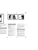
Door stand
Rope
Door stand
Rope
Tighten to
25-28Nm
9
Do not allow people to walk under or
around the door during the installation
process as serious injury can occur.